


Quick Research
Generate reliable direction feasibility study reports for your R&D in just a few steps.

Technical Q&A
Discover and master advanced knowledge NOW. Basics, ideas, possibilities, all at once.

Find Solutions
As an expert in R&D theories, this can generate solutions to your technical problems instantly.

Evaluate Feasibility
Analyze your overall solution with one click, know your potential R&D risks in advance.

Monitor Landscape
Get weekly tech updates, stay abreast of the latest tech innovations and key insights.
Autostereoscopic display
A visual display, naked-eye stereo technology, applied in stereo systems, stereo photography, instruments, etc., can solve problems such as wide interval, unevenness, stereo effect or image quality damage.
- Summary
- Abstract
- Description
- Claims
- Application Information
AI Technical Summary
Problems solved by technology
Method used
Image

Examples
Embodiment 1
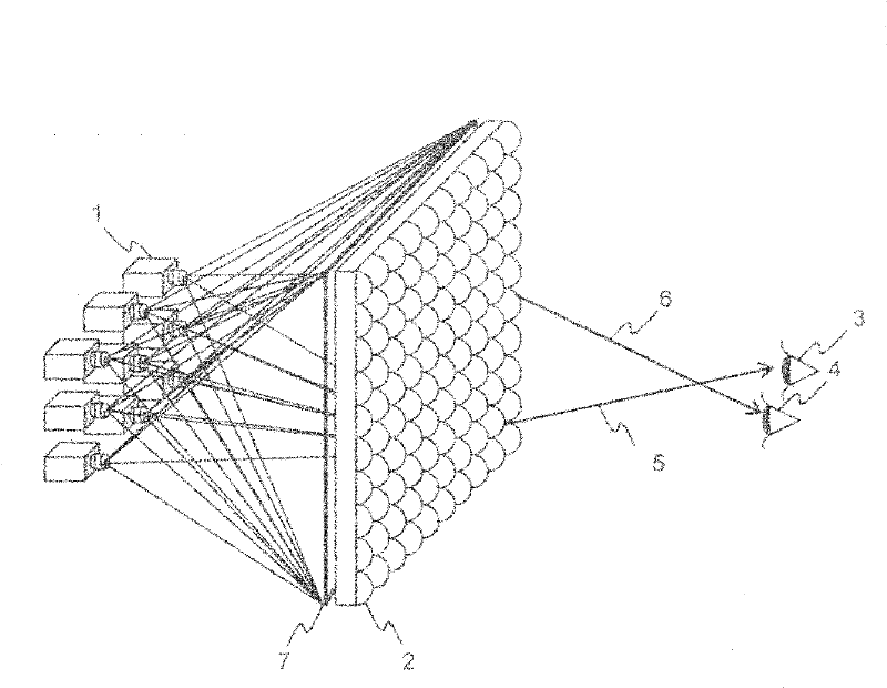
[0023] Regarding the embodiment in the case where a microlens array is used as a condensing optical device, a diffusion plate is used as a diffusion device, and a projector is used as an image projection device, use figure 1 to explain.
[0024] Superimposed projection is performed from the projector group 1 to the microlens array 2 . people at figure 1 View the direction of the microlens array from the position of the right eye 3 and the left eye 4. The light emitted from the projector group 1 is diffused by the diffuser plate 7 , then enters the microlens array 2 , is once condensed, and then diffused as a directional light. A part of the light emitted from the projector (5 and 6 in the figure) selectively enters the left and right eyes of a person according to their positions, and by outputting information with parallax as light information, stereoscopic viewing can be performed with the naked eye.
[0025] use image 3 and Figure 4 , the effect of the diffusion plate...
Embodiment 2
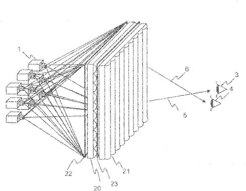
[0053] Next, use figure 2 , to describe an embodiment using a biconvex lens as a light-condensing optical device. exist figure 2 in, instead of figure 1 The microlens array uses 2 lenticular lens sheets (20,21 among the figure). Two diffusion plates are used, the diffusion plate 22 is provided at the focus position of the lenticular lens sheet 20 , and the diffusion plate 23 is provided at the focus position of the lenticular lens sheet 21 . The imaging range of the projector (the range of the focal depth of the projector including the imaging position of the light from the projector) is sufficiently wider than the focal length of the lenticular lens, so the lenticular lens sheets 20, 21 can only be provided within the imaging range of the projector. , Diffusion plates 22 and 23 are sufficient.
[0054] As shown in this embodiment, by using a lenticular lens, the lens intervals in the up-down direction and in the left-right direction can be separately set, and the number...
Embodiment 3
[0057] As another example, a holographic optical element utilizing the diffraction effect may also be used as the light-condensing optical device. The holographic optical element can also be used like the above-mentioned bi-convex lens, and can also be made into a thin plate by combining bidirectional light-condensing optical devices. Therefore, the diffuser plate is made into one piece, and it only needs to be installed at the focal point of the holographic optical element.
PUM
 Abstract
Description
Claims
Application Information
 - R&D Engineer
- R&D Manager
- IP Professional
- Industry Leading Data Capabilities
- Powerful AI technology
- Patent DNA Extraction
Browse by: Latest US Patents, China's latest patents, Technical Efficacy Thesaurus, Application Domain, Technology Topic, Popular Technical Reports.
© 2024 PatSnap. All rights reserved.Legal|Privacy policy|Modern Slavery Act Transparency Statement|Sitemap|About US| Contact US: help@patsnap.com