Projector

A projector and projection lens technology, applied in the field of projectors, can solve the problems of affecting the projector's projection brightness, not being used, and wasting light.

Inactive Publication Date: 2012-04-11
HONG FU JIN PRECISION IND (SHENZHEN) CO LTD +1
View PDF4 Cites 2 Cited by
  • Summary
  • Abstract
  • Description
  • Claims
  • Application Information

AI Technical Summary

Problems solved by technology

The P polarized light will directly pass through the polarization plane of the polarized beam splitting prism and refract the group of polarized beam splitting prisms, which cannot be utilized.
That is

Method used


Image

  • Projector
  • Projector
  • Projector

Examples


Embodiment Construction

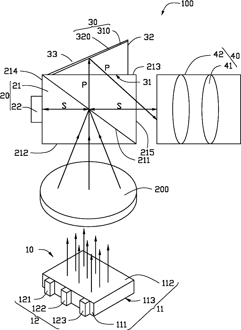
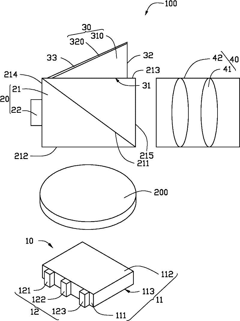
[0037] see figure 1 , the projector 100 provided by the embodiment of the present invention includes a light source module 10 , a polarization splitting module 20 , a reflection device 30 and a projection lens 40 .

[0038] The light source module 10 includes a light guide plate 11 and a light emitting unit 12 . The light guide plate 11 is roughly square, and has a light incident surface 111, a light exit surface 112, and a reflective surface 113. The reflective surface 113 is arranged opposite to the light exit surface 112. 113 are connected to each other, and reflective dots are arranged on the reflective surface 113 . The light emitting unit 12 is located on one side of the light incident surface 111 , and the light emitting unit 12 includes a red light source 121 , a green light source 122 and a blue light source 123 . The red light source 121 , green light source 122 and blue light source 123 are red LED, green LED and blue LED respectively. The light emitted by the li...


PUM


Abstract

The projector comprises a light source module, a polarization beam splitting module and a projection lens. The polarization beam splitting module, which is arranged to be right opposite to the light source module, is used for receiving lights emitted by the light source module. The polarization beam splitting module comprises a set of polarized beam splitters (PBS) and an LCOS panel; and each of the PBS is formed by two isosceles right-angle prisms, wherein a polarization plane is formed between the two contact surfaces; besides, each of the PBS also includes: a light incidence plane, which is opposite to the light source module; a first surface, which is opposite to the light incidence plane; a reflection plane; and a light emission plane, which is opposite to the reflection plane. The LCOS panel is arranged on the reflection plane. In addition, the projector also includes a reflection apparatus. The reflection apparatus is arranged on the first surface of the PBS and is used for reflecting a polarized light that is transmitted from the polarization plane of the PBS to the projection lens. According to the invention, the projector enables a P polarized light to be utilized, so that a light utilization rate is improved and projection brightness is also enhanced.

Description

technical field [0001] The present invention relates to a projector. Background technique [0002] LCOS projection technology is an emerging technology that combines semiconductor technology and liquid crystal display. It has the advantages of small size and low power consumption, and is often embedded in mobile phones for projection. A conventional LCOS imaging system generally includes a light source, a set of polarization beam splitters (PBS), an LCOS panel and a projection lens. After the S-polarized light and P-polarized light emitted by the light source perpendicular to each other enter the group of polarized beamsplitters, the S-polarized light will be reflected by the polarization plane of the grouped polarized beamsplitter to the LCOS panel for modulation, and then it will be modulated by other polarized beamsplitters. After reflection, it enters the projection lens. However, the P polarized light will directly pass through the polarization surface of the polariz...

Claims


Application Information

Patent Timeline
IPC IPC(8): G03B21/28G03B21/20G02B27/28G02B5/08F21V7/22F21V13/00F21V17/00F21Y101/02
Inventor 黄雍伦
Owner HONG FU JIN PRECISION IND (SHENZHEN) CO LTD
Why Eureka
Try Eureka