
Illumination system and projection device

A lighting system and projection device technology, applied in projection devices, photography, color photography, etc., can solve problems such as brightness loss of projection systems

Pending Publication Date: 2022-05-31
CORETRONIC
View PDF10 Cites 0 Cited by
  • Summary
  • Abstract
  • Description
  • Claims
  • Application Information

AI Technical Summary

Problems solved by technology

Therefore, the biggest impact on the projection system is the loss of brightness due to the light valve being closed.

Method used


Image

  • Illumination system and projection device
  • Illumination system and projection device
  • Illumination system and projection device

Examples


Embodiment Construction

[0022] The aforementioned and other technical contents, features and effects of the present invention will be clearly presented in the following detailed description of a preferred embodiment with reference to the accompanying drawings. The directional terms mentioned in the following embodiments, such as: up, down, left, right, front or back, etc., are only referring to the directions of the drawings. Accordingly, the directional terms are used to illustrate and not to limit the invention.

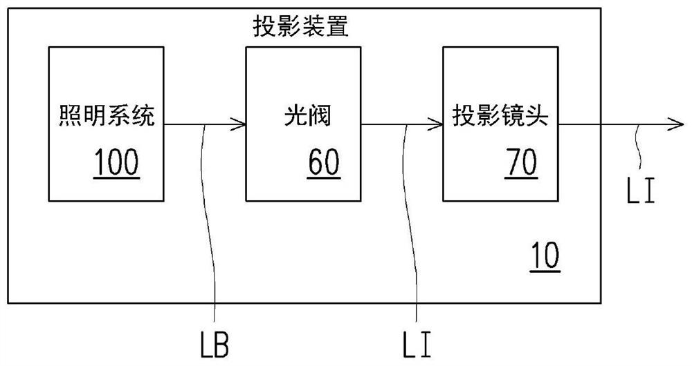
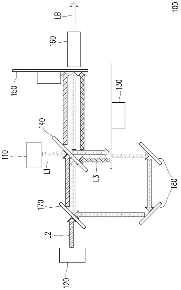
[0023] figure 1 It is a schematic diagram of a projection device according to an embodiment of the present invention. Please refer to figure 1 . This embodiment provides a projection device 10 including an illumination system 100 , at least one light valve 60 and a projection lens 70 . Wherein, the lighting system 100 is used for providing the lighting beam LB. At least one light valve 60 is disposed on the transmission path of the illumination beam LB for converting the illumination...


PUM


Abstract

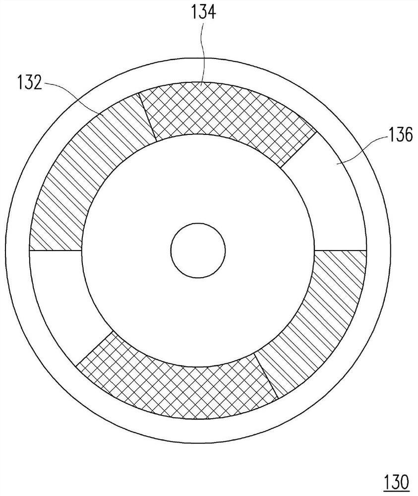
The invention discloses an illumination system and a projection device using the illumination system. The illumination system is used for providing an illumination light beam and comprises a blue light source, a red light source, a wavelength conversion device, a first light splitting element, a light filtering device and a light uniformizing element. The blue light source is used for providing a blue excitation beam. The red light source provides a red light beam. The wavelength conversion device is used for converting the blue excitation light beam into an excited light beam. The first light splitting element is used for enabling one of the blue excitation light beam and the excited light beam to pass through and reflecting the other. The light filtering device comprises a light filtering area. The light filtering device is located between the first light splitting element and the light uniformizing element, the blue excitation light beam, the excited light beam and the red light beam are sequentially transmitted to the light filtering device and the light uniformizing element to form an illumination light beam, and the excited light beam and the red light beam pass through the light filtering area at different time sequences. The illumination system and the projection device can increase the projection brightness.

Description

technical field [0001] The present invention relates to an optical system and an electronic device, and in particular to an illumination system and a projection device. Background technique [0002] A projection device is a display device used to generate a large-scale picture, and has been continuously improving with the evolution and innovation of science and technology. The imaging principle of the projection device is to convert the illumination beam generated by the lighting system into an image beam through a light valve, and then project the image beam to a projection target (such as a screen or a wall) through a projection lens to form a projection image. [0003] In addition, the lighting system has also changed from ultra-high-performance lamps (UHP lamps) to light-emitting diodes (Light- emitting diode (LED), has evolved to the most advanced laser diode (laser diode, LD) light source. In the current optical system, since the current high-brightness green laser d...

Claims


Application Information

Patent Timeline
Patent Type & Authority Applications(China)
IPC IPC(8): G03B21/20
CPCG03B21/2013G03B21/204G02B26/008G02B27/141G03B33/08G03B21/2066G03B21/2053
Inventor 潘浩炜
Owner CORETRONIC
Learn More