Charging member, process unit cartridge, and image forming apparatus

一种充电部件、导电性的技术,应用在电晕放电装置、电气元件、电路等方向,达到电阻变化率降低、图像品质优、表面性质改善的效果

Active Publication Date: 2012-04-11
FUJIFILM BUSINESS INNOVATION CORP
View PDF5 Cites 2 Cited by
  • Summary
  • Abstract
  • Description
  • Claims
  • Application Information

AI Technical Summary

Problems solved by technology

However, this charger produces ozone and nitrogen oxides

Method used


Image

  • Charging member, process unit cartridge, and image forming apparatus
  • Charging member, process unit cartridge, and image forming apparatus
  • Charging member, process unit cartridge, and image forming apparatus

Examples


Embodiment 1 to 11 and comparative example 1 to 3

[0062] 1. Make the charging roller

[0063] 1-1. Making a metal shaft

[0064] A drawn metal tube having an outer diameter of 8 mm was cut to a length of 330 mm and subjected to electroless nickel plating to produce a metal shaft.

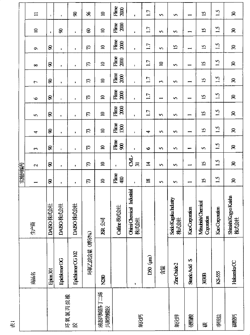
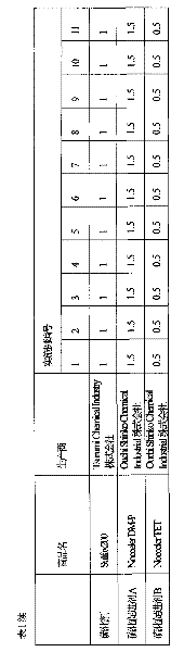
[0065] 1-2 Formation of conductive elastic layer

[0066]The ingredients shown in the following Tables 1 and 2 (units are weight ratios) were kneaded in a tangential pressure kneader (available from Moriyama Co., Ltd.) with a net chamber capacity of 75 liters, and then kneaded in a 22-inch open mill Kneading in to obtain unvulcanized rubber flakes. The unvulcanized rubber sheet is extruded by a single-screw rubber extruder (cylinder inner diameter: 60mm; L / D: 20) with a crosshead die (inner diameter: 12mm, die mouth diameter: 8mm), while the metal shaft is continuously Through this crosshead die, the extruded unvulcanized rubber is thus coated on the metal shaft. The rotation speed of the screw was 15 rpm, and the temperatures at the barrel, sc...


PUM


Abstract

A charging member includes a conductive metal shaft and a conductive elastic layer. The conductive elastic layer comprises a rubber material containing 50% to 100% by weight of epichlorohydrin rubber containing 56 mol % or more of an ethylene oxide and a calcium oxide having an average particle size D50 of 18 [mu]m or smaller. The invention also provides a process unit cartridge and an image forming apparatus having the charging member.

Description

technical field [0001] The present invention relates to a charging member, a processing unit case, and an image forming apparatus. Background technique [0002] Most of the existing electrophotographic image forming apparatuses (such as copiers and printers) use chargers utilizing the phenomenon of corona discharge, such as scorotrons. However, this charger produces ozone and nitrogen oxides. Therefore, as a charger for an electrophotographic image forming apparatus, a contact type charger that charges an image carrier by bringing a conductive charging member into direct contact with the image carrier has been widely used in recent years. [0003] From the standpoint of attaining higher speed, higher image quality, and longer life, there is an increasing need for a charging member with lower resistance for use in a contact charger. The charging member has heretofore been manufactured by molding a rubber material by pressurization or injection molding, vulcanizing it, and t...

Claims


Application Information

Patent Timeline
Patent Type & Authority Applications(China)
IPC IPC(8): G03G15/02G03G21/18G03G15/00
CPCG03G15/0233G03G2215/0132G03G15/02G03G21/18C08L71/03C08K3/22
Inventor 六反实泊省吾
Owner FUJIFILM BUSINESS INNOVATION CORP
Why Eureka
Try Eureka