Plastic injection molding with moveable insert members

a technology of insert members and plastic injection molding, which is applied in the field of plastic injection molding, can solve the problems of sink marks and other surface defects, increase the weight, material usage, cycle time of the article, and difficulty in providing a satisfactory molded articl

Inactive Publication Date: 2005-09-06
INT AUTOMOTIVE COMPONENTS GRP NORTH AMERICA INC
View PDF100 Cites 46 Cited by
  • Summary
  • Abstract
  • Description
  • Claims
  • Application Information

AI Technical Summary

Benefits of technology

[0008]It is a still further object of the present invention to provide a method and system for gas assist injection molding which eliminates the need for spillover cavities and the subsequent capture and regrinding of excess plastic material from a mold cavity. It is an additional object of the present invention to provide a moveable insert in a mold cavity and allow packing of the plastic material in the mold for better dimensional and surface effects.

Problems solved by technology

The rib members are typically thicker than the molded article which increases the weight, material usage, and cycle time of the article, and often induces sink marks and other surface defects due to a thermal gradients in the area of the thickened section.
Where the rib members or other portions of the article in which the gas is being introduced are elongated, it is often difficult to provide a satisfactory molded article.
For example, if the pressure of the gas is too great as it enters the mold cavity, there is a risk that it may rupture or blow out the plastic within the mold cavity, i.e. the gas is not contained within the plastic.
Also, it is often difficult to have the gas migrate along the full length of an elongated, thicker plastic section, thus creating a product which has an uneven thickness and cooling cycle.

Method used


Image

  • Plastic injection molding with moveable insert members
  • Plastic injection molding with moveable insert members
  • Plastic injection molding with moveable insert members

Examples


Embodiment Construction

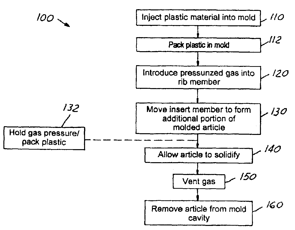
[0028]The present invention is particularly suitable for producing hollow rib structures for structural reinforcement of decorative or non-decorative trim components and panels using gas-assist plastic injection molding.

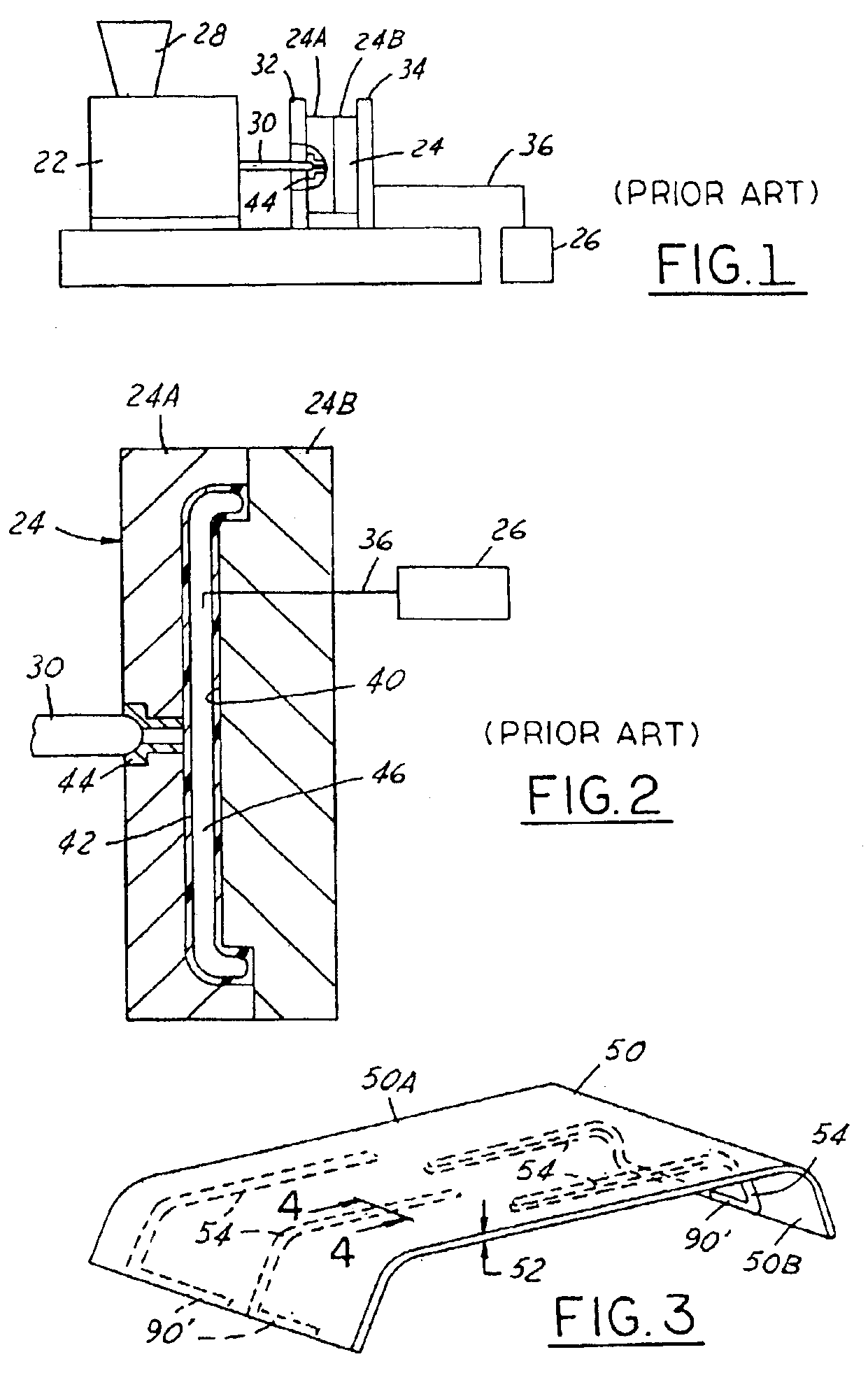
[0029]As shown in FIG. 1, a conventional plastic injection molding system 20 is shown. The system 20 includes an injection molding machine 22, a mold 24, and a source of gas 26 for the gas assisted injection molding. As is well known in the injection molding field, injection molding machine 22 has a hopper 28 in which plastic pellets are added to the machine. The injection molding machine includes a mechanism for melting the plastic material and a screw-type ram (not shown) in the body of the machine. The molten plastic material is injected through a nozzle 30 into the mold 24.

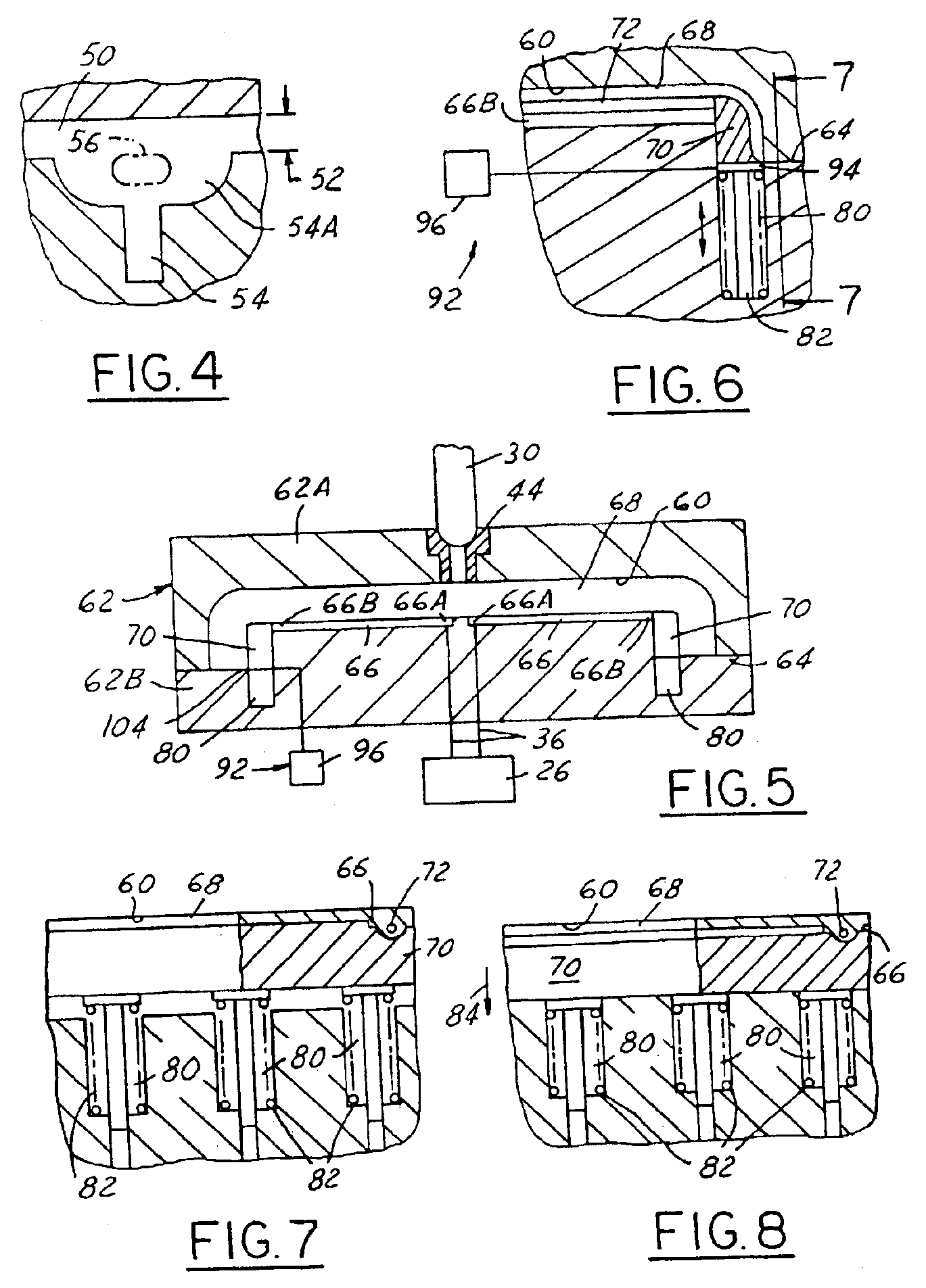
[0030]Mold 24 includes two mold halves 24A and 24B. The two mold halves are connected to platens 32 and 34 which separate and come together as one or more is moved on the injection molding mach...


PUM

PropertyMeasurementUnit
fill pressureaaaaaaaaaa
areaaaaaaaaaaa
pressureaaaaaaaaaa

Abstract

A method and system for producing hollow rib structures for trim components and panels using gas assisted injection molding. Movable insert members are provided in the mold cavity, particularly at the ends of the structural rib members. After the plastic material is injected into the mold cavity, the plastic is packed in the mold, and the insert members are locked in position. Selectively activatable locking mechanisms are used to lock up the insert members. Thereafter, gas or another fluid is introduced into the rib members in order to provide hollow channels therein. Movement of the insert members provides a recess or groove for placement of the displaced resin from the rib members. The displaced resin material completes the formation of the molded plastic article.

Description

CROSS REFERENCE TO RELATED APPLICATIONS[0001]This is a continuation-in-part of U.S. patent application Ser. No. 10 / 249,237 filed on Mar. 25, 2003.BACKGROUND OF INVENTION[0002]The present invention relates to plastic injection molding and more particularly to plastic injection molding using gas assist and the formation of hollow rib members on plastic injection molded parts.[0003]In the plastic injection molding art, the usual challenges facing the product designer include designing an article having the requisite strength for the product application and satisfactory surface finish, as well as avoiding excessive weight, surface distortions, and increased cycle time. For flat or thin products, it is typical to include one or more rib members in the design to provide relative strength and structure for the molded article. The rib members are typically thicker than the molded article which increases the weight, material usage, and cycle time of the article, and often induces sink marks ...

Claims


Application Information

Patent Timeline
Patent Type & Authority Patents(United States)
IPC IPC(8): B29C45/17
CPCB29C45/1705
Inventor HOMANN, GREGORY A.HENDRY, JAMESTURCZYNSKI, DAVID
Owner INT AUTOMOTIVE COMPONENTS GRP NORTH AMERICA INC
Why Eureka
Try Eureka