[0009]An object of the invention is to provide a rack shaft support device capable of absorbing fluctuations in meshing while also being able to reliably inhibit the generation of sound over a long period of time.
[0011]The intermediate member is rotated by the
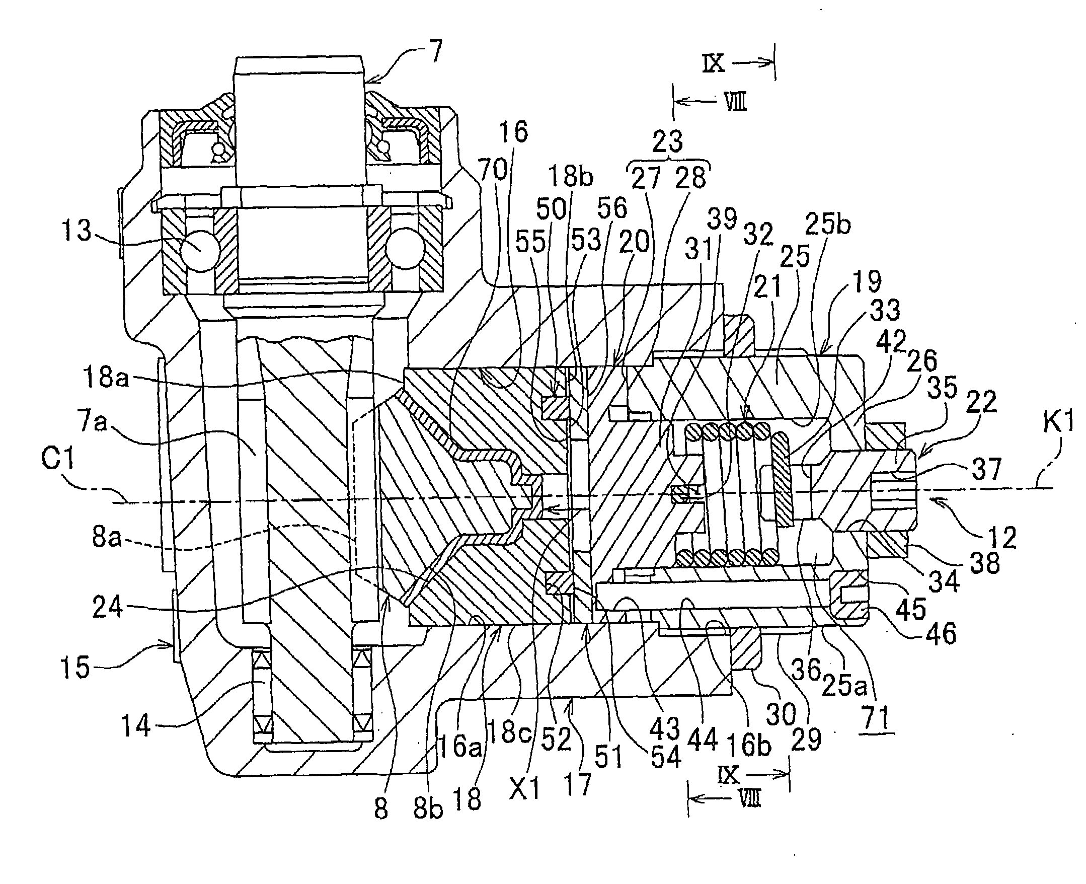
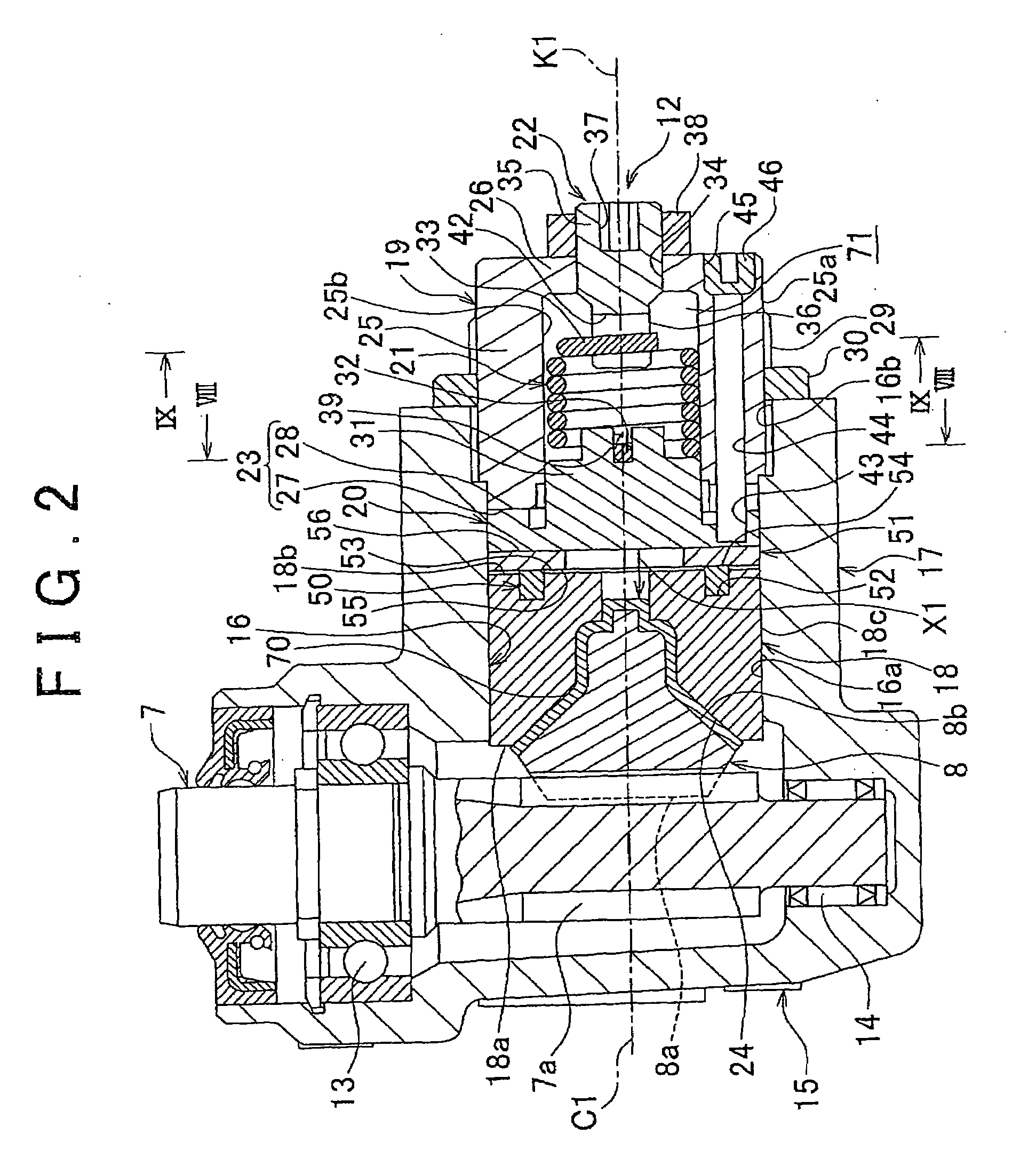
torsion spring accompanying progression of wear between the sliding portions of the rack shaft support member and the rack shaft. Since the intermediate member pushes the rack shaft support member towards the rack shaft by the action of the
cam mechanism accompanying rotation of the intermediate member, pushing force of the meshing portions of the
rack and pinion can be maintained roughly constant. Thus, generation of rattling sound can be inhibited over a long period of time. Moreover, fluctuations in meshing between the
rack and pinion can be absorbed by increasing or decreasing the amount of the gap formed between the rack shaft support member and the opposing portion accompanying expansion and contraction of the annular elastic member. Thus, even after the intermediate member has moved the rack shaft support member towards the rack shaft due to the action of the torsion spring accompanying the progression of wear between the sliding portions as described above, backlash between the
rack and pinion is made to be extremely low, thereby preventing steering resistance from becoming excessively large.
[0013]In addition, in the rack shaft support device as claimed in the above-mentioned aspect, an annular concave portion may be formed in the rear surface of the rack shaft support member, the annular elastic member may be held in the annular concave portion, the cross-sectional shape of the annular elastic member may be quadrangular, and the annular elastic member may have an annular flat surface opposing the opposing portion. In this case, the annular elastic member is able to secure a large surface area that makes
sliding contact with the opposing portion (or with an annular plate to be described later in the case an annular plate is interposed between the intermediate member and the annular elastic member), thereby making it possible to prevent permanent set in fatigue of the annular elastic member and improve durability of the annular elastic member.
[0015]In addition, in the rack shaft support device as claimed in the above-mentioned aspect, the opposing member may be an annular plate, the annular plate may respectively include a first surface and a second surface in the axial direction of the annular plate, the first surface of the annular plate may contact the annular elastic member, the second surface of the annular plate may contact the intermediate member, and frictional force between the second surface of the annular plate and the intermediate member may be made to be smaller than the frictional force between the first surface of the annular plate and the annular elastic member. In this case, during rotation of the intermediate member,
sliding contact is made between the intermediate member and the second surface of the annular plate for which frictional force is relatively small. As a result, the intermediate member is able to rotate smoothly as required.
[0016]In order to reduce frictional force between the second surface of the annular plate and the intermediate member, the surface properties of the second surface may be improved over those of the first surface such as by improving the roughness accuracy (enhancing smoothness) of the second surface, and
zinc plating, fluororesin
coating or other surface treatment for reducing the
friction coefficient may be carried out on the second surface. The surface area of which
sliding contact is made with the intermediate member may also be reduced by providing annular projections in the second surface, or a
lubricant such as
grease may be interposed between the second surface and the intermediate member.
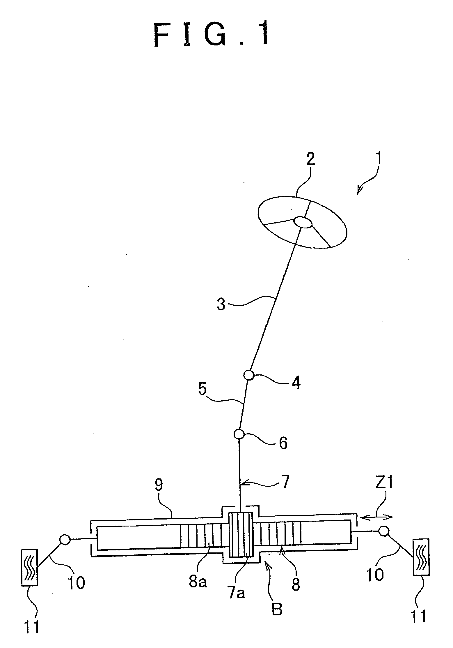
[0017]In addition, the above-mentioned rack shaft support device may be applied to a vehicle steering apparatus that supports a rack shaft so as to be able to slide in the axial direction. In this aspect, a vehicle steering apparatus is achieved that is capable of inhibiting increases in steering resistance by absorbing fluctuations in meshing between the rack and pinion, and preventing the generation of rattling sound over a long period of time.

