Control apparatus and method of controlling internal combustion engine mounted on vehicle

a technology of control apparatus and internal combustion engine, which is applied in the direction of electric control, machines/engines, speed sensing governors, etc., can solve the problems of engine not serving as a braking force, large driving force applied to the driving wheels of the vehicle, and taking a long time to stop the vehicle from traveling

Inactive Publication Date: 2013-04-02
TOYOTA JIDOSHA KK
View PDF9 Cites 5 Cited by
  • Summary
  • Abstract
  • Description
  • Claims
  • Application Information

AI Technical Summary

Benefits of technology

[0012]The invention provides a control apparatus and a method of controlling an internal combustion engine mounted on a vehicle that stop the vehicle from traveling as swiftly as possible while suppressing the stalling of the internal combustion engine upon a shift of engine operation to idle operation in the process of stopping the vehicle from traveling.
[0013]In a first aspect of the invention, a control apparatus for an internal combustion engine mounted on a vehicle that executes an engine idle speed control for adjusting the engine speed to a target engine speed set in accordance with a magnitude of a drive request value for an auxiliary driven by the internal combustion engine when the vehicle speed is equal to or below a predetermined speed to idle the internal combustion engine, in a process of stopping the vehicle from traveling, reduces the drive request value for the auxiliary during performance of the engine idle speed control, and reduces the target engine speed by a value equivalent to a reduction in the drive request value after lapse of a prescribed delay time from a time point corresponding to start of reduction of the drive request value. The control apparatus includes detection means for detecting whether the vehicle is traveling on a road surface with low friction coefficient, and engine speed reduction means for reducing the target engine speed by the value equivalent to the reduction in the drive request value before lapse of the delay time if it is determined that the vehicle is traveling on a road surface with low friction coefficient.
[0014]If the speed of the vehicle is equal to or below the predetermined speed to idle the internal combustion engine mounted on the vehicle in the process of stopping the vehicle from traveling, the target engine speed for the engine idle speed control is reduced by the value equivalent to the reduction in the drive request value for the auxiliary based on the reduction of the drive request value. Thus, the vehicle is swiftly stopped from traveling. If the vehicle is traveling on a road surface with low friction coefficient upon a shift of the internal combustion engine to the idle operation, even if the target engine speed is reduced by the value equivalent to the reduction in the drive request value for the auxiliary after the drive request value is reduced and before the delay time elapses, the internal combustion engine is unlikely to stall. This is because there is a small amount of disturbance acting on driving wheels in such a direction as to stop rotation thereof on a road surface with low friction coefficient. For example, a relatively small external force (a relatively small frictional force or the like) from the road surface side acts on the driving wheels opposite the rotational direction thereof on a road surface with a low friction coefficient. As a result, the engine speed is hardly reduced due to the disturbance. According to the foregoing configuration, if the vehicle is traveling on a road surface with low friction coefficient, the target engine speed is reduced by the value equivalent to the reduction in the drive request value for the auxiliary before the lapse of the delay time as described above. If the vehicle is not traveling on a road surface with low friction coefficient, the target engine speed is reduced after the lapse of the delay time. Thus, the vehicle may be stopped as swiftly as possible while suppressing the occurrence of a stall of the internal combustion engine upon a shift of engine operation to idle operation in the process of stopping the vehicle from traveling.

Problems solved by technology

In this case, since the rotational speed of the engine during idle operation is high as described above, the driving force applied to driving wheels of the vehicle is large.
As a result, it takes some time to stop the vehicle from traveling.
As a result, the rotational resistance of the internal combustion engine does not serve as a braking force for the driving wheels.
However, such a braking force cannot always be ensured by using the brake alone.
It takes some time to stop the vehicle from traveling when the braking force cannot be ensured with ease.
In that case, the internal combustion engine may undergo a stall as a result of a further reduction in the rotational speed of the engine caused by the disturbance.
However, when the predetermined delay time is set between the time point corresponding to reduction of the drive request value for the auxiliary and the time point corresponding to reduction of the target rotational speed for idle rotational speed control in response thereto upon a shift of engine operation to idle operation in the process of stopping the vehicle from traveling, the time needed to stop the vehicle from traveling is prolonged by the delay time.
As a result, it is difficult to swiftly stop the vehicle from traveling.
In this case, however, the possibility of the internal combustion engine undergoing a stall inevitably becomes high.

Method used


Image

  • Control apparatus and method of controlling internal combustion engine mounted on vehicle
  • Control apparatus and method of controlling internal combustion engine mounted on vehicle
  • Control apparatus and method of controlling internal combustion engine mounted on vehicle

Examples


first embodiment

[0029]The first embodiment in which the invention is applied to an engine mounted on a rear-wheel-drive automobile will be described hereinafter with reference to FIGS. 1 to 3.

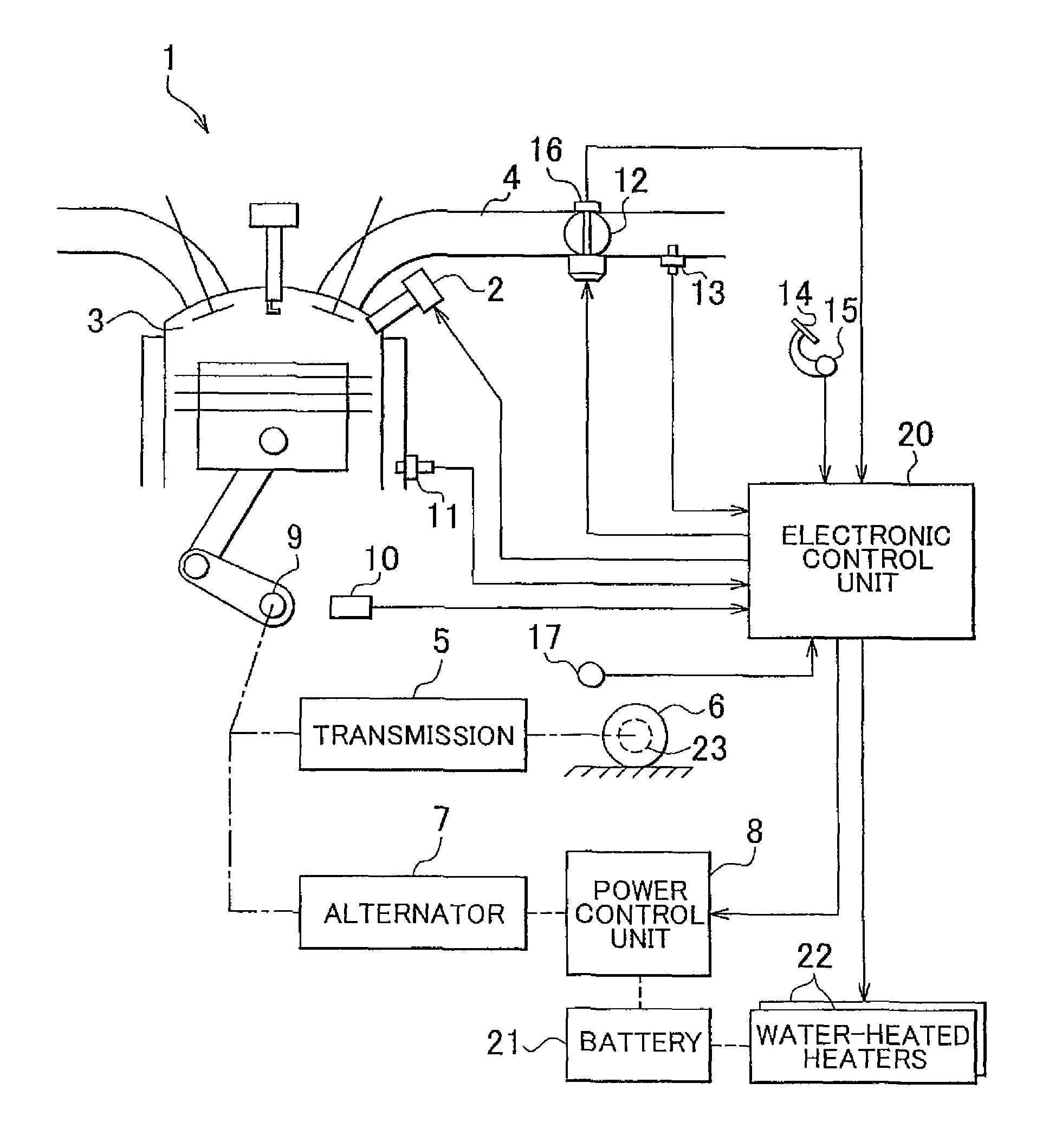
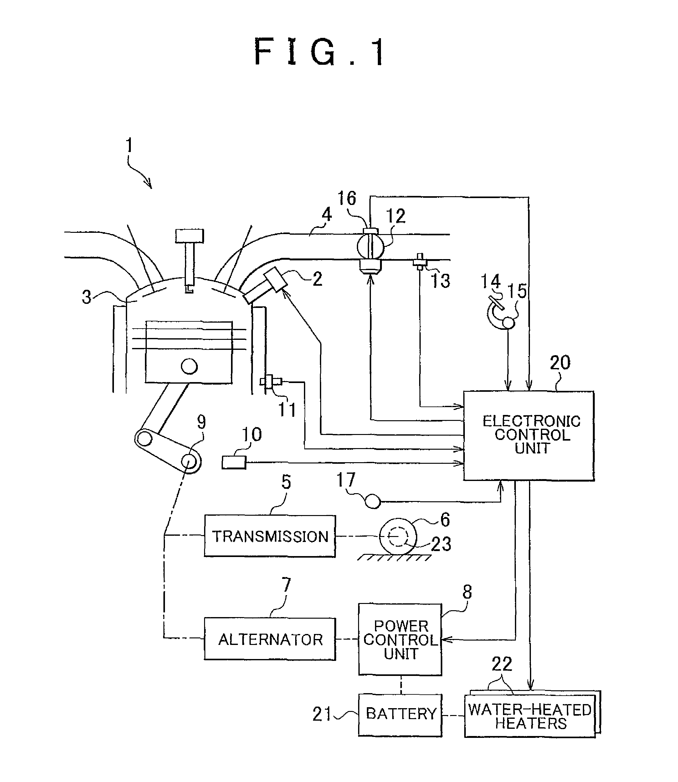
[0030]In an engine 1 shown in FIG. 1, air is drawn from an intake passage 4 into a combustion chamber 3, and an amount of fuel appropriate for this intake air amount is injected from a fuel injection valve 2 and supplied to the combustion chamber 3. Thus, as the amount of intake air increases through the adjustment of the opening degree of a throttle valve 12 provided in the intake passage 4, the amount of the mixture burned in the combustion chamber 3 increases and the power output of the engine increases. A crankshaft 9 as an output shaft of the engine 1 is connected to the driving wheels (rear wheels) 6 of the automobile via a drive train that includes a transmission 5 such as an automatic transmission or the like. A brake 23 applies a braking force to the driving wheels 6 for stopping the rotation of the d...

second embodiment

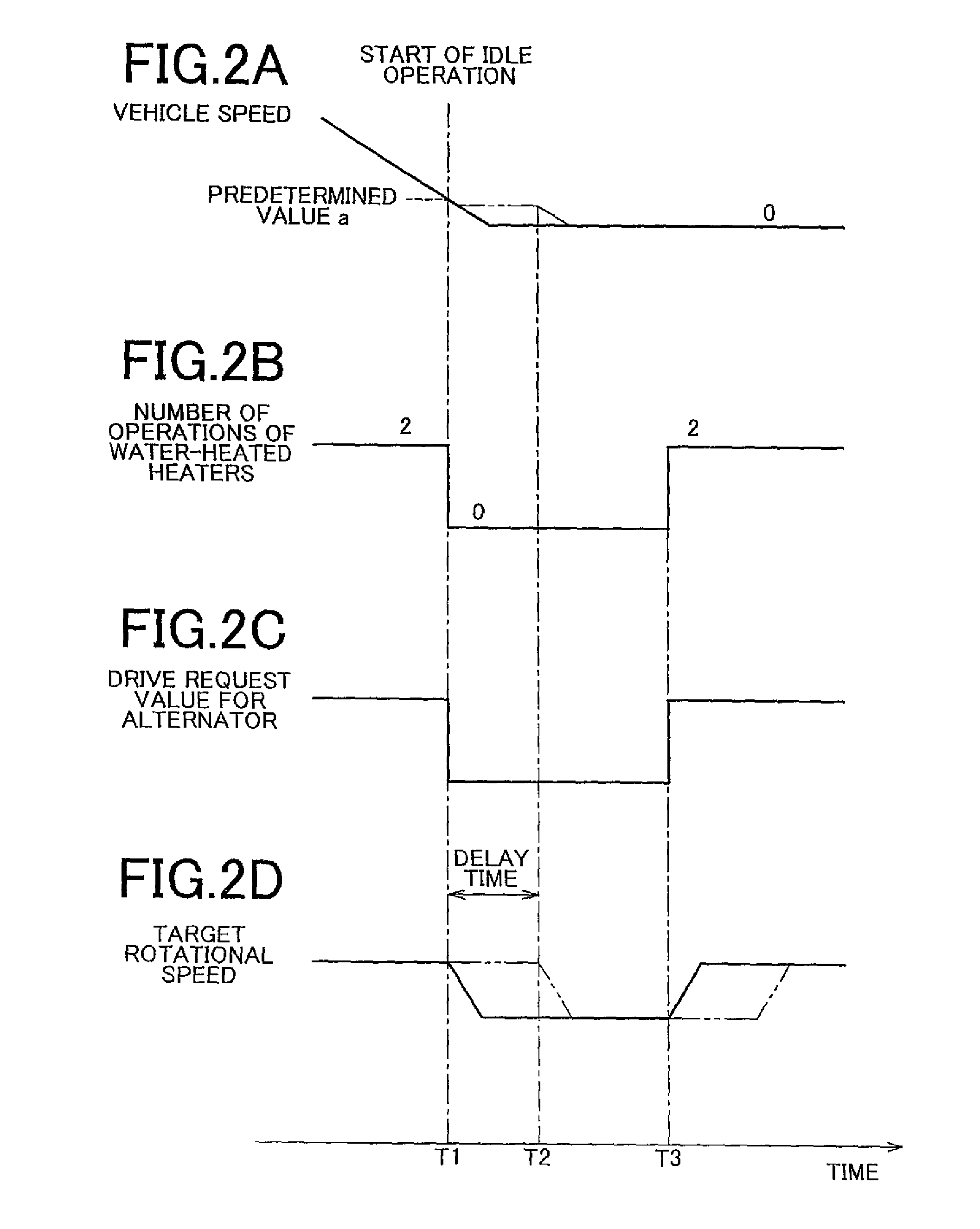
[0055]Next, the invention will be described with reference to FIGS. 4A to 4D. When the drive request value for the auxiliary is large upon a shift of the engine 1 to idle operation in the process of stopping the automobile, the target engine speed is also high. Therefore, the drive request value for the auxiliary is reduced rapidly and drastically, and the target engine speed is also reduced rapidly and drastically on the basis of reduction of the drive request value. In this case, if the drive rate of the auxiliary cannot be reduced in good response to a drastic reduction in the drive request value for the auxiliary, reducing the target engine speed by a value equivalent to the reduction in the drive request value before the lapse of a delay time, when the automobile is traveling on a road surface with low friction coefficient, may cause the engine 1 to stall. That is, high rotational resistance is produced in the engine 1 to drive the auxiliary during a period in which there is a ...


PUM


Abstract

When an automobile is traveling on a road surface with a low friction coefficient upon a shift of an engine to idle operation in the process of stopping the automobile from traveling, a target engine speed of the engine is reduced by a value equivalent to a reduction in a drive request value for any auxiliary at a time point corresponding to start of reduction of the drive request value.

Description

BACKGROUND OF THE INVENTION[0001]1. Field of the Invention[0002]The invention relates to a control apparatus and a method of controlling an internal combustion engine mounted on a vehicle.[0003]2. Description of the Related Art[0004]In an internal combustion engine mounted on a vehicle such as an automobile or the like, if the speed of the vehicle is equal to or below a predetermined speed to make a shift to idle operation in the process of stopping the vehicle from traveling, an idle speed control for adjusting the engine speed to a target engine speed during idle operation is performed. The target rotational speed used in this idle rotational speed control is variably set in accordance with the magnitude of a driving request for an auxiliary driven by the internal combustion engine. The target rotational speed is set higher as the driving request for the auxiliary increases. The target rotational speed is thus made variable in accordance with the magnitude of the driving torque fo...

Claims


Application Information

Patent Timeline
Patent Type & Authority Patents(United States)
IPC IPC(8): F02D29/02F02D41/00F02D41/16
CPCF02D31/003F02D31/008F02D41/083F02D41/12F02D2200/702
Inventor TSUNOOKA, TAKASHISHOGENJI, YOSHIYUKI
Owner TOYOTA JIDOSHA KK
Why Eureka
Try Eureka