Vehicle braking device

A braking device and vehicle technology, applied in the direction of control device, brake, control drive, etc., can solve problems such as passenger discomfort, and achieve the effect of preventing the generation of whine

Inactive Publication Date: 2012-04-11
HONDA MOTOR CO LTD
View PDF6 Cites 9 Cited by
  • Summary
  • Abstract
  • Description
  • Claims
  • Application Information

AI Technical Summary

Problems solved by technology

[0005] When switching from regenerative braking to hydraulic braking, especially when the hydraulic braking force suddenly rises when the vehicle speed is low, the slipping of the brake pads and the brake discs will cause "gooing". noise (so-called honk), which may cause discomfort to passengers

Method used


Image

  • Vehicle braking device
  • Vehicle braking device
  • Vehicle braking device

Examples


no. 1 approach

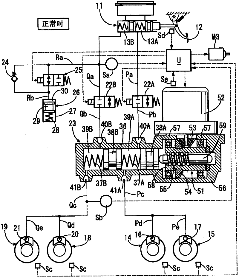
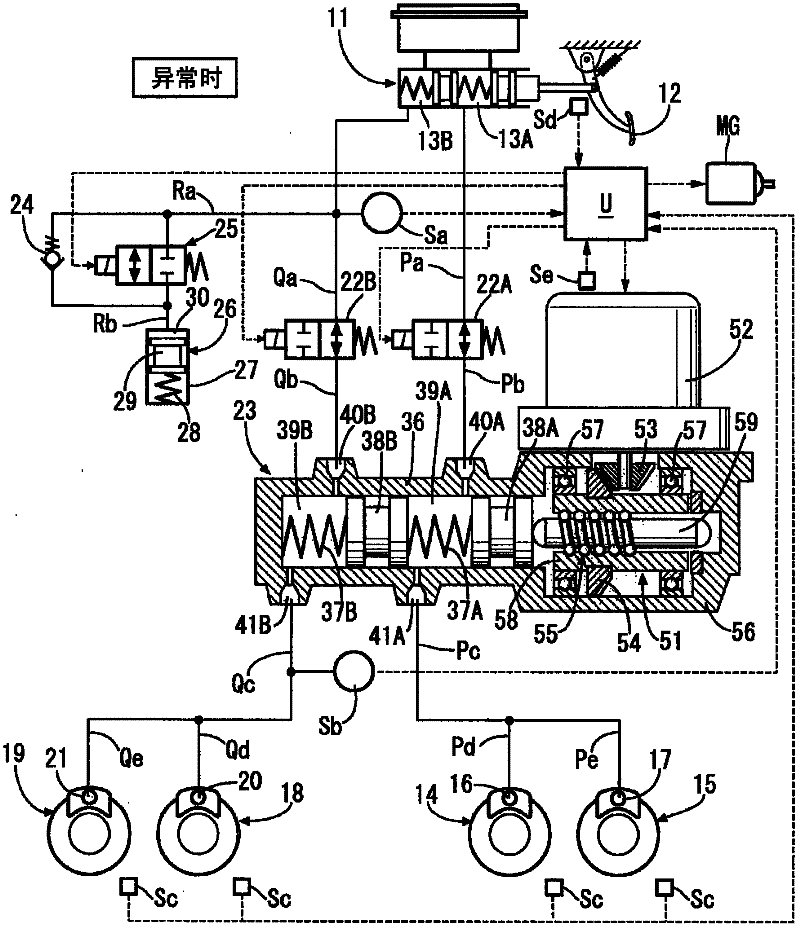
[0032] Such as figure 1 As shown, the tandem-type master hydraulic cylinder 11 is provided with a sub-hydraulic chamber 13A and a main hydraulic chamber 13B that output brake hydraulic pressure corresponding to the driver's depressing force on the brake pedal 12, and the sub-hydraulic chamber 13A passes through the hydraulic passages Pa, Pb . Qe is connected to the wheel cylinders 20, 21 of the disc brake devices 18, 19 of the right front wheel and the left rear wheel, for example.

[0033] An on-off valve 22A as a normally open electromagnetic valve is arranged between the liquid paths Pa and Pb, and an on-off valve 22B as a normally open electromagnetic valve is arranged between the liquid paths Qa and Qb. A slave hydraulic cylinder 23 is arranged between the hydraulic passages Pc and Qc. Further, a stroke simulator 26 is connected to the hydraulic passages Ra and Rb branched from the hydraulic passage Qa extending from the main hydraulic chamber 13B via a reaction force a...


PUM


Abstract

In a vehicle capable of regenerative braking and hydraulic braking, during changeover from regenerative braking to hydraulic braking in response to a reduction in the vehicle speed due to braking, the hydraulic braking force is increased from zero at a first increasing rate when the vehicle speed is lower than or equal to a first threshold (V1), and the hydraulic braking force is increased at a second increasing rate that is higher than the first increasing rate when the vehicle speed is lower than or equal to a second threshold (V2) that is lower than the first threshold (V1). With this, a wheel cylinder can be prevented from squeaking by setting the first increasing rate of the hydraulic braking force to a small value, and, at the same time, a necessary braking force can be generated without any problems by setting the second increasing rate of the subsequent hydraulic braking force to a large value.

Description

technical field [0001] The present invention relates to a braking device for a vehicle including a regenerative braking device and a hydraulic braking device capable of performing both regenerative braking and hydraulic braking, that is, a vehicle that switches from regenerative braking to hydraulic braking after the start of braking. Braking device. Background technique [0002] According to the following Patent Document 1, there is known a BBW (brake-by-wire) brake device in which the operation of the brake pedal by the driver is converted into an electric signal, and a slave that operates based on the electric signal The brake hydraulic pressure generated by the dynamic hydraulic cylinder is used to activate the wheel brake cylinder, and as a backup when the slave hydraulic cylinder fails, a master hydraulic cylinder that operates through the brake pedal is installed. When the slave hydraulic cylinder is normal, the stroke simulation is used. The device absorbs the brake...

Claims


Application Information

Patent Timeline
Patent Type & Authority Applications(China)
IPC IPC(8): B60T8/17B60L7/24B60T8/00
CPCB60T1/10B60W2520/10B60W10/184B60T8/00B60L7/26B60L7/18B60W10/08B60L7/24B60T8/4081B60W30/18127B60T2270/604B60L15/2009B60L2240/12Y02T10/64Y02T10/72
Inventor 松下悟史
Owner HONDA MOTOR CO LTD
Why Eureka
Try Eureka