
Flux generator

A generator and flux technology, applied in the direction of welding equipment, auxiliary welding equipment, welding/cutting auxiliary equipment, etc., can solve the problems of shortened service life, affecting the use effect, inconvenient cleaning, etc., to prolong the service life, facilitate cleaning, The effect of simple structure

Inactive Publication Date: 2012-04-18
NANTONG ZHONGLIAN S&T SERVICE
View PDF0 Cites 1 Cited by
  • Summary
  • Abstract
  • Description
  • Claims
  • Application Information

AI Technical Summary

Problems solved by technology

[0002] At present, the flux generator that everyone is familiar with includes the main body, the flange cover connected to the upper end of the main body, the air inlet pipe and the air outlet pipe connected to the flange cover. After the equipment is used for a period of time, some flux residues will be left at the bottom of the main body. It must be cleaned, but in the cleaning process, the flange cover and the body need to be separated, which is inconvenient to clean and the cleaning effect is not good. There is no valve installed on the intake pipe, and the Leakage, shortened service life

Method used


Image

  • Flux generator
  • Flux generator

Examples


Embodiment approach

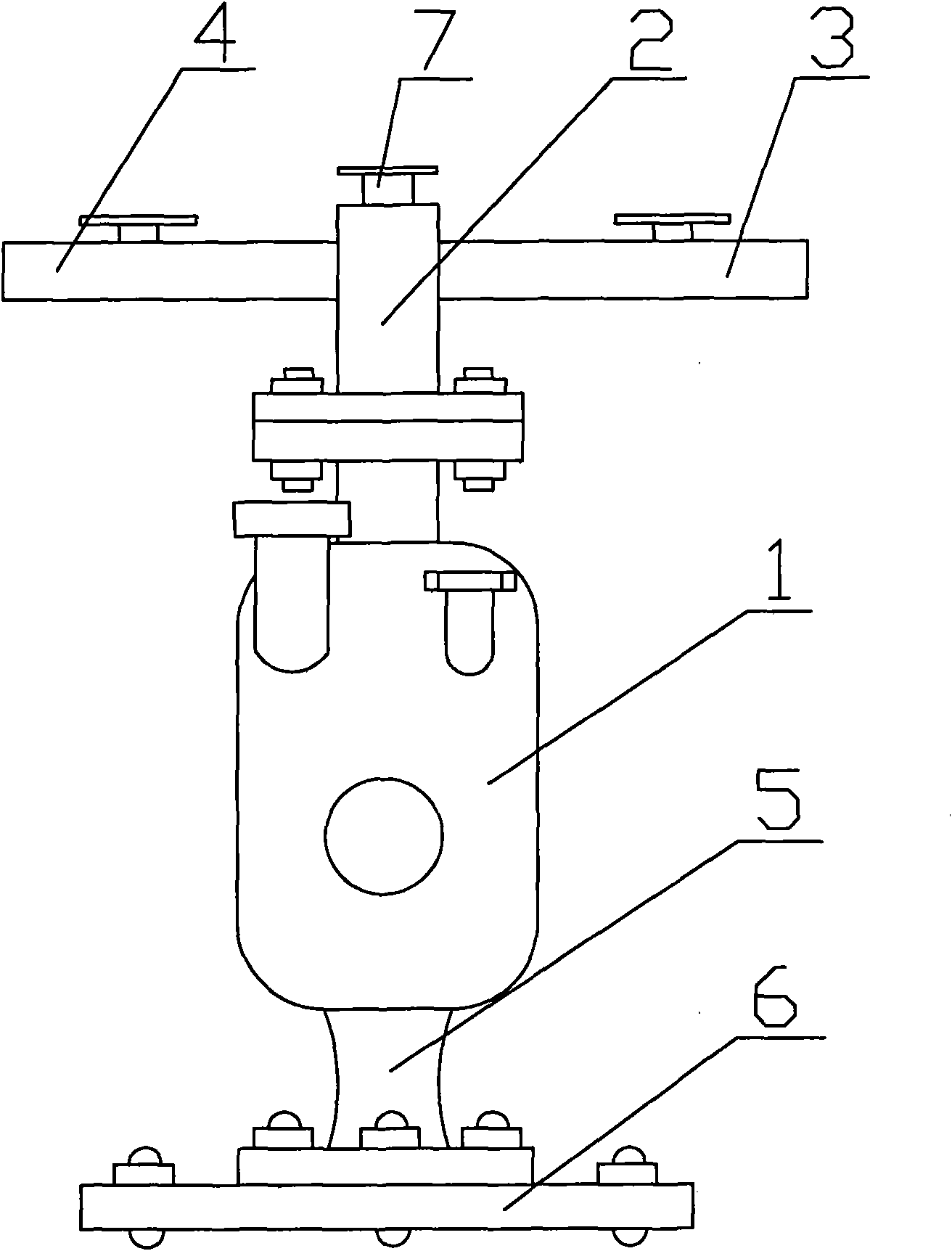
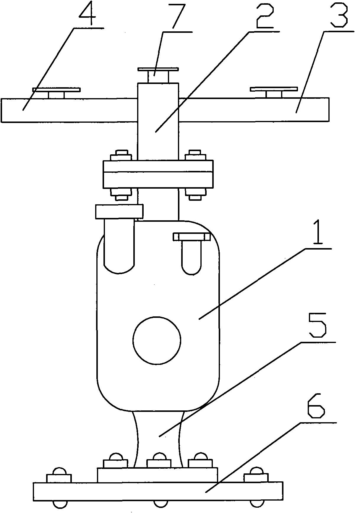
[0010] Such as figure 1 An embodiment of the flux generator of the present invention is shown, including a main body 1, a flange cover 2 is vertically provided on the upper end of the main body 1, an air inlet pipe 3 is provided on one side of the upper end of the flange cover 2, and an air inlet pipe 3 is provided on the upper end of the flange cover 2. The other side of the upper end is provided with an air outlet pipe 4, the top of the flange cover 2 is provided with a valve 7, the air inlet pipe 3 and the air outlet pipe 4 are also provided with a valve 7 respectively, the lower end of the body 1 is connected with a hollow flange seat 5, and the hollow The flange seat 5 is connected with a chassis 6 by screws.

[0011] When in use, combustible gas enters the body 1 containing flux through the inlet pipe 3, and the gas mixed with the flux flows out from the outlet pipe 4. After working for a period of time, the generated flux residue passes through the hollow flange seat 5 ...


PUM


Abstract

The invention discloses a flux generator, which comprises a body. The upper end of the body is vertically provided with a flange cover, one side of the upper end of the flange cover is provided with a gas intake pipe, the other side of the upper end of the flange cover is provided with a gas discharging pipe, the top end of the flange cover is provided with a valve, the gas intake pipe and the gas discharging pipe are respectively provided with a valve, the lower end of the body is connected with a hollow flange base, and the hollow flange base is connected with a chassis through a screw. The invention has the advantages that the flux generator has a simple structure, the cleaning can be facilitated, the service life can be prolonged, and the flux quality can be improved.

Description

Technical field: [0001] The invention relates to a flux generator, which belongs to the technical field of welding equipment. Background technique: [0002] At present, the flux generator that everyone is familiar with includes the main body, the flange cover connected to the upper end of the main body, the air inlet pipe and the air outlet pipe connected to the flange cover. After the equipment is used for a period of time, some flux residues will be left at the bottom of the main body. It must be cleaned, but in the cleaning process, the flange cover and the body need to be separated, which is inconvenient to clean and the cleaning effect is not good. There is no valve installed on the intake pipe, and the Leakage phenomenon shortens the service life. Invention content: [0003] The object of the present invention is to overcome the above disadvantages and provide a flux generator with simple structure, easy cleaning, prolonging service life and improving flux quality. ...

Claims


Application Information

Patent Timeline
IPC IPC(8): B23K37/00
Inventor 管林林吴惠松
Owner NANTONG ZHONGLIAN S&T SERVICE
Learn More