
Non-jumper-connection optical cable cross connecting box

A technology of optical cable transfer box and jumper, which is applied in the direction of fiber mechanical structure, etc., can solve the problems of inconvenient management, messy, high wiring pressure, etc., to solve the problem of messy wiring, promote development, reduce communication failure points and insertion loss Effect

Inactive Publication Date: 2012-04-18
SUZHOU NEW SEA UNION TELECOM TECH CO LTD
View PDF3 Cites 9 Cited by
  • Summary
  • Abstract
  • Description
  • Claims
  • Application Information

AI Technical Summary

Problems solved by technology

The traditional optical cable transfer box has a large wiring pressure, is easy to be messy, and is inconvenient to manage
With the development of optical networks, the number of clients and bandwidth requirements have reached a new height, and the traditional optical cable transfer box can no longer meet the requirements

Method used


Image

  • Non-jumper-connection optical cable cross connecting box
  • Non-jumper-connection optical cable cross connecting box
  • Non-jumper-connection optical cable cross connecting box

Examples


Embodiment Construction

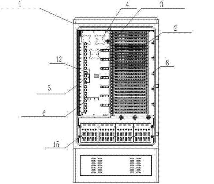
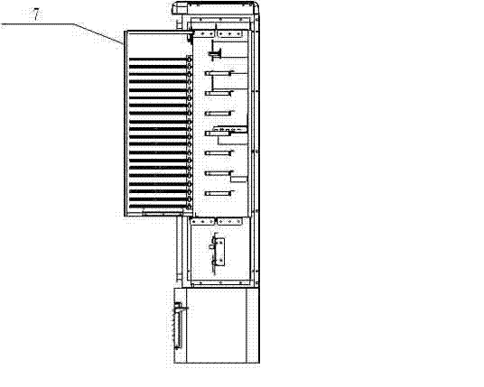
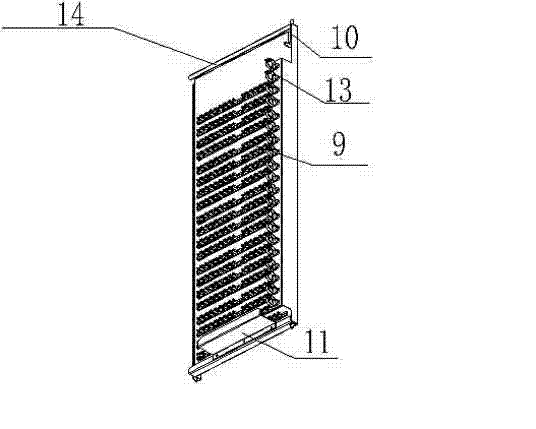
[0013] Figure 1-3 A jumper-free optical cable transfer box is shown, including a box body 1, a 12-core fusion-matching integrated tray 2 is provided on the right side of the inner rear wall of the box body 1, and a 12-core fusion-matched integrated tray 2 is provided on the left side. Two jumper rings 3, the top left side of the inner rear wall of the box body 1 is provided with a fiber winding tube 4, and the left side of the middle part of the inner rear wall of the box body 1 is provided with a box-type optical splitter installation box 5, the box The box-type optical splitter installation box 5 is equipped with a box-type optical splitter 12, a third jumper ring 6 is provided under the inner rear wall of the box body 1, and a rotating ring 6 is provided on the left side wall of the box body 1. Connected optical splitter pigtail plug management unit 7, a first jumper ring 8 is provided on the right side wall of the box body 1, and an optical cable fixing and stripping unit...


PUM


Abstract

The invention relates to a non-jumper-connection optical cable cross connecting box. The non-jumper-connection optical cable cross connecting box is characterized by comprising a box body, wherein the right side of a rear wall in the box body is provided with a two-core fusion and distribution integrated tray, and the left side of the two-core fusion and distribution integrated tray is provided with a second jumper ring; the left side of the rear wall in the box body is provided with a fiber coiling barrel, the left side at the middle part of the rear wall in the box body is provided with a box type optical branching device mounting box, and a box type optical branching device is mounted in the box type optical branching device mounting box; a third jumper ring is arranged under the rear wall in the box body, and the left sidewall in the box body is provided with a rotationally connected optical branching device tail fiber plug management unit; a first jumper ring is arranged at the right sidewall in the box body, and an optical cable fixed stripping unit is arranged under the box body. The box type optical branching device meets the requirement of point-to-point and point-to-multipoint comprehensive development of the optical fiber, communication fault points and insertion loss are reduced, network security is improved, the defects of small wiring capacity and easily disordered layout are solved, and development of optical networks is promoted.

Description

technical field [0001] The invention relates to a cabinet used in the communication industry, in particular to a jumper-free optical cable transfer box applied to outdoor optical cable connections. Background technique [0002] The traditional optical transfer box currently used, that is, the full jumper optical cable transfer box is the interface device at the junction of the backbone optical cable and the distribution optical cable in the optical fiber access network. It is mainly used for the connection, distribution and scheduling of outdoor optical cables. The functions of splicing, terminal, storage and dispatching etc. A new type of distribution device that can fix, splice, jump, protect and manage single-core, bundled and loose-core optical cables. It is one of the important supporting equipment for realizing fiber to the roadside, fiber to the building and fiber to the user. The traditional optical cable transfer box has high wiring pressure, is easy to be messy, ...

Claims


Application Information

Patent Timeline
Patent Type & Authority Applications(China)
IPC IPC(8): G02B6/44
Inventor 瞿正南王海其
Owner SUZHOU NEW SEA UNION TELECOM TECH CO LTD
Learn More