Method and system for realizing flow migration

A flow migration and flow-carrying technology, applied in security devices, electrical components, wireless network protocols, etc., can solve the problem of no uplink and downlink IP flow migration

Inactive Publication Date: 2012-04-18
ZTE CORP
View PDF3 Cites 16 Cited by
  • Summary
  • Abstract
  • Description
  • Claims
  • Application Information

AI Technical Summary

Problems solved by technology

[0030] 2. Architecture of non-3GPP access to EPC 2
However, there is currently no solution for migrating uplink and downlink IP flows from non-3GPP access networks / 3GPP access networks to 3GPP access networks / non-3GPP access networks

Method used


Image

  • Method and system for realizing flow migration
  • Method and system for realizing flow migration
  • Method and system for realizing flow migration

Examples


Embodiment 1

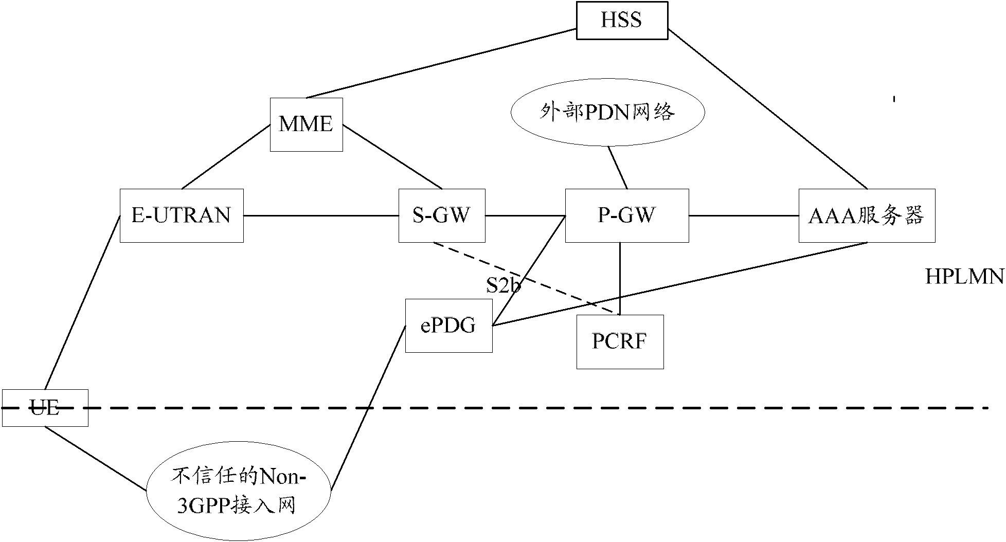
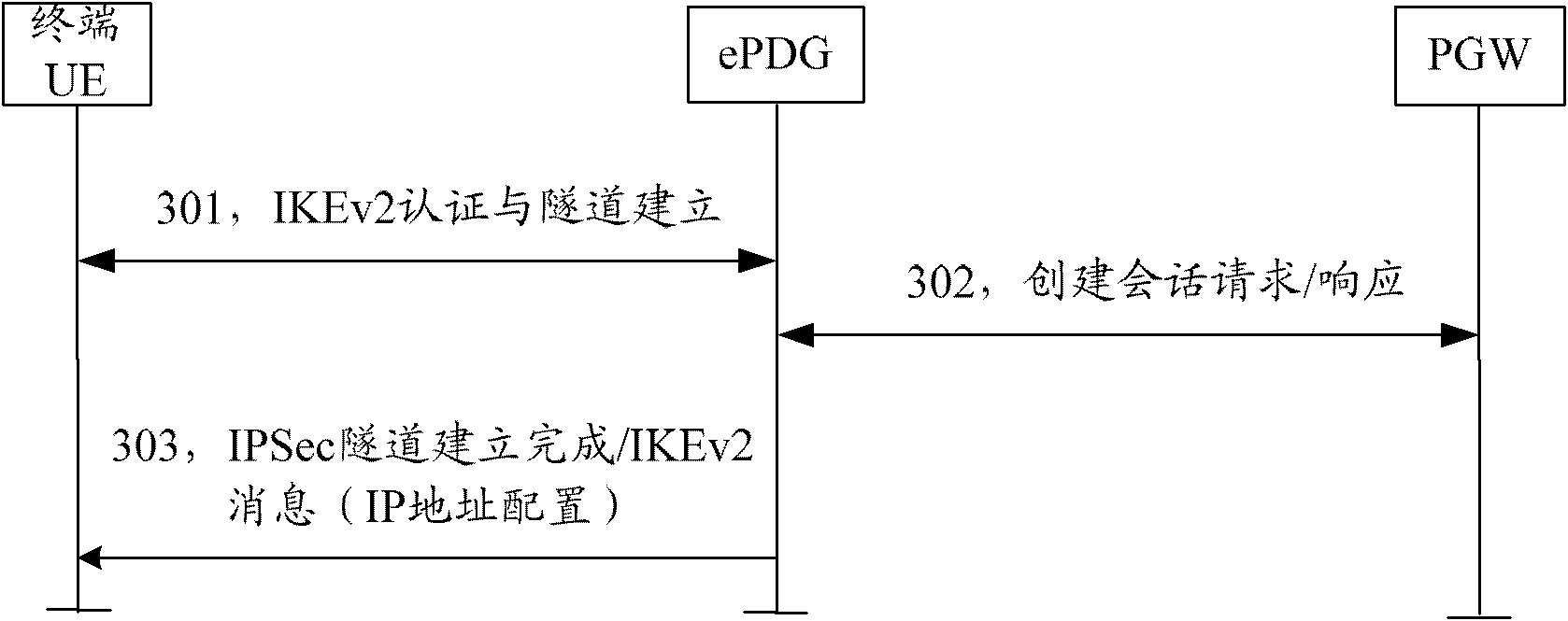
[0216] In this embodiment, the terminal UE first attaches in the 3GPP access network and establishes one or more PDN connections; after that, the terminal UE initiates an attach / PDN connection establishment operation in the non-3GPP access network (such as image 3 , 5 shown), to realize multiple bindings of the same PDN connection.

[0217] In steps 301-302 and steps 501-502, when establishing multiple bindings of the same PDN connection, the terminal UE carries an "Access Identify (AID)" to the P-GW, and the P-GW acquires the AID , establishing multiple bindings with the 3GPP access network and the non-3GPP access network.

[0218] After receiving the session creation request message sent by the ePDG and analyzing the AID, the P-GW establishes a GTP tunnel with the ePDG and maintains the GTP tunnel between the P-GW and the S-GW. In the "session creation response" message returned to the ePDG, the P-GW returns the IP address allocated to the terminal UE to the terminal UE t...

Embodiment 2

[0269] In this embodiment, the terminal UE needs to carry different AIDs no matter when it accesses the first network to initiate attachment / PDN connection establishment, or when it accesses the second network to initiate multiple bindings of the same PDN connection. For example, the terminal UE first accesses the 3GPP access network, and when the first PDN connection is established, it is assigned AID-1, and when the terminal UE initiates multiple binding of the PDN connection in the second network, it is assigned AID-1. 2. During the lifetime of the PDN connection, AID-1 indicates the 3GPP access network, and AID-2 indicates the non-3GPP access network.

[0270] In addition, multiple PDN connections established by the terminal UE are also allocated with different AIDs.

[0271] When the terminal UE / network side migrates / creates / deletes service flows in different access networks, in addition to carrying flow migration information / flow description information, it also carries ...

Embodiment 3

[0282] In the system based on the above embodiment 1 and embodiment 2, the data channel / tunnel is established between the ePDG and the P-GW through the GTP protocol. As mentioned in the background technology, the PMIPv6 protocol can still be used between the ePDG and the P-GW Establishment of data channels / tunnels. The present invention is also applicable when the PMIPv6 protocol is used between the ePDG and the P-GW. The basic mechanism is the same as the GTP scenario, the difference is through Figure 15 The description for further clarification.

[0283] Step 1500 to Step 1501: Same as Step 700 to Step 701.

[0284] Step 1502: the ePDG sends PBU signaling to the P-GW, and carries the flow migration information.

[0285] Flow migration information can be carried in PMIPv6 messages by adding new cells. Existing PBU messages do not support carrying QoS information. Therefore, flow migration information needs to be carried in extended cells.

[0286] Step 1503: After receiv...


PUM


Abstract

The invention discloses a method and system for realizing flow migration, wherein a terminal UE (User Equipment)/a network side can request the network side or the terminal UE to perform the flow migration by means of a 3GPP (The 3rd Generation Partnership Project) access network or a non-3GPP access network; and the terminal UE and the network side are used for correspondingly migrating uplink/downlink IP (Internet Protocol) flows to the 3GPP access network via the non-3GPP access network or to the non-3GPP access network via the 3GPP access network. Accordingly, the method and system for realizing the flow migration, disclosed by the invention, can be used for realizing the switching between the non-3GPP access network and the 3GPP access network, and thus, the system flexibility and efficiency can be increased.

Description

technical field [0001] The present invention relates to the communication field, in particular to a method and system for realizing flow migration. Background technique [0002] In order to maintain the strong competitiveness of the third generation mobile communication system in the field of mobile communication, it is necessary to improve its network performance and reduce the cost of network construction and operation. Therefore, the standardization working group of the 3rd Generation Partnership Project (3rdGeneration Partnership Project, 3GPP) Currently working on the next generation evolution of the core network system - Evolved Packet Core (EPC), the purpose is to provide users with higher transmission rates and shorter transmission delays. The EPC system supports the access of the Evolved Universal Terrestrial Radio Access Network (E-UTRAN); the EPC system supports the access of the Non-3GPP access network, such as the Wireless Local Area Network (WLAN) Access Netwo...

Claims


Application Information

Patent Timeline
Patent Type & Authority Applications(China)
IPC IPC(8): H04W36/14H04W36/24
CPCH04W80/045H04W12/04H04W36/14H04W12/0471
Inventor 毕以峰朱春晖周娜王静赵佑春吴瑟刘建业王卫斌
Owner ZTE CORP
Why Eureka
Try Eureka