
LED (light-emitting diode) dimming driving circuit

A dimming drive and circuit technology, which is applied in the layout of electric lamp circuits, light sources, electric light sources, etc., can solve the problems of poor output current accuracy, limited dimming range, and inability to dim the LED dimming drive circuit, and achieves an average current. The effect of stability, wide dimming range and large average current range

Active Publication Date: 2012-04-18
BCD (SHANGHAI) MICRO ELECTRONICS LTD
View PDF3 Cites 37 Cited by
  • Summary
  • Abstract
  • Description
  • Claims
  • Application Information

AI Technical Summary

Problems solved by technology

[0004] At present, the dimming range of LED dimming driving circuits on the market is limited, and it is impossible to realize dimming within the full line voltage range; in addition, there are some LED dimming driving circuits with poor output current accuracy, so the reliability of LED light sources is affected. great influence

Method used


Image

  • LED (light-emitting diode) dimming driving circuit
  • LED (light-emitting diode) dimming driving circuit
  • LED (light-emitting diode) dimming driving circuit

Examples


Embodiment Construction

[0063] In order to enable those skilled in the art to better understand the technical solutions in the present application, the technical solutions in the embodiments of the present application will be clearly and completely described below in conjunction with the drawings in the embodiments of the present application. Obviously, the described The embodiments are only some of the embodiments of the present application, but not all of them. Based on the embodiments in this application, all other embodiments obtained by persons of ordinary skill in the art without creative efforts shall fall within the scope of protection of this application.

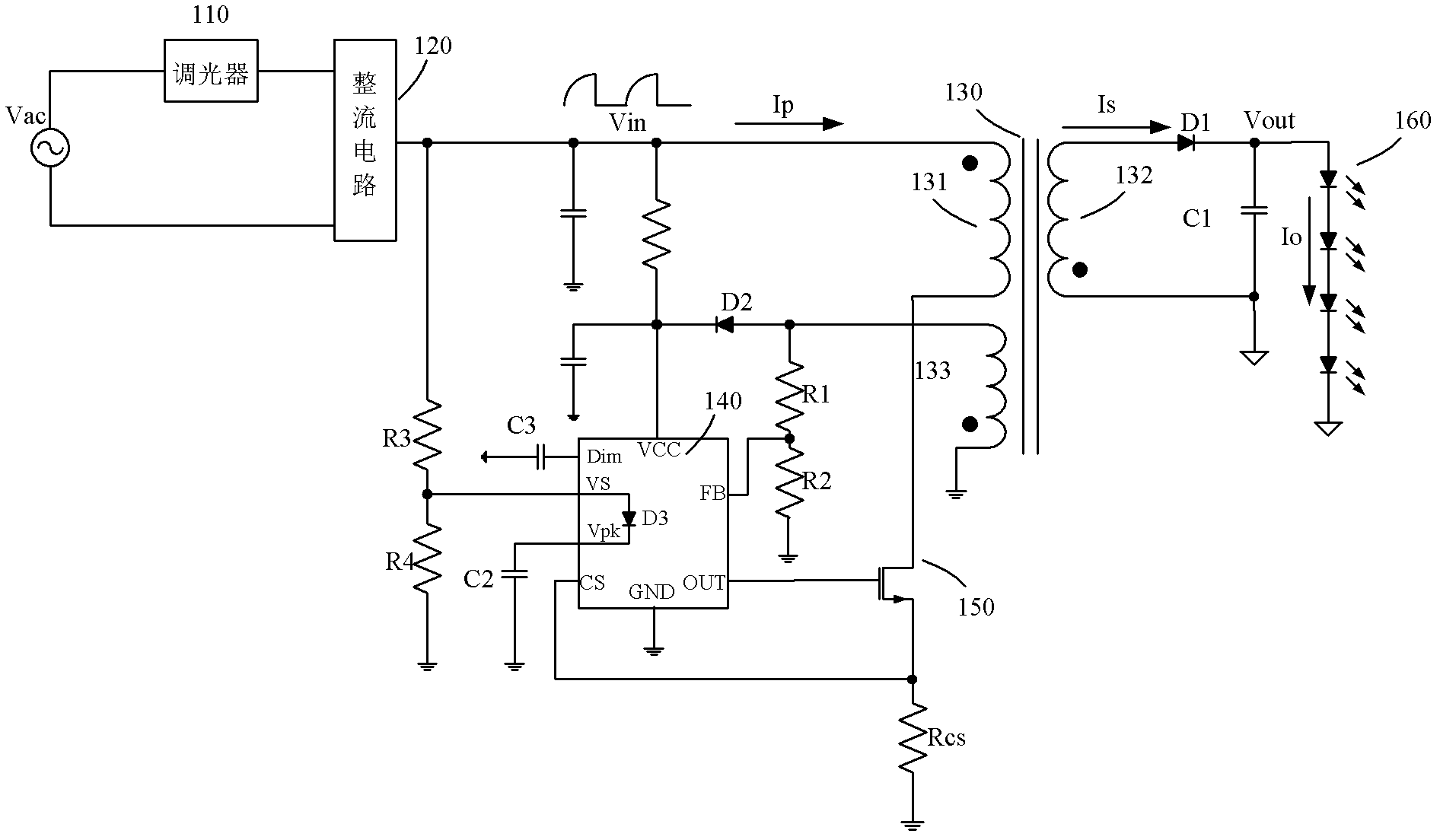
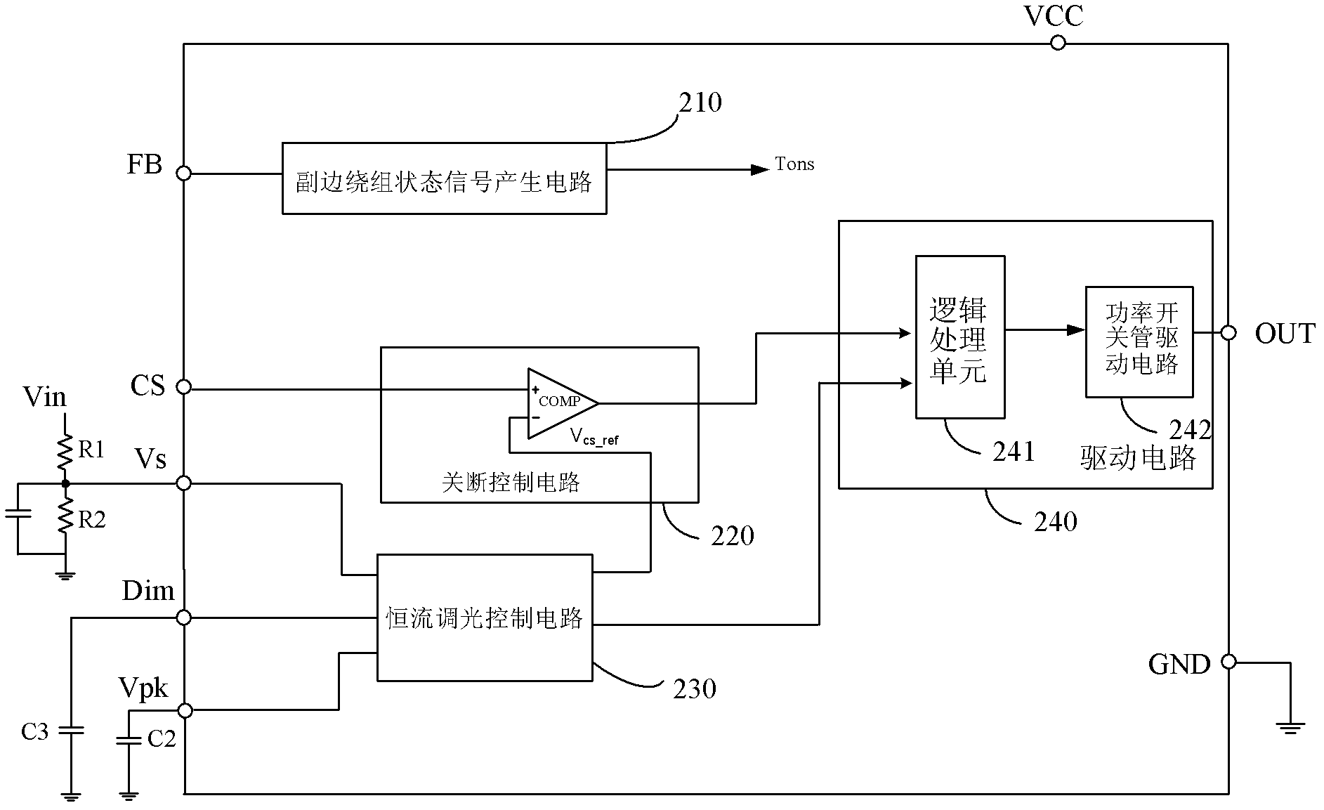
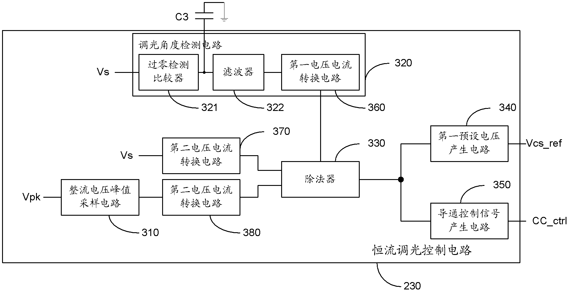
[0064] See figure 1 , shows a schematic diagram of the circuit principle of an LED dimming drive circuit according to an embodiment of the present application, the circuit includes: a dimmer 110, a rectifier circuit 120, a transformer 130, a control circuit 140, and a power switch tube 150, wherein:

[0065] The input end of the dimmer 1...


PUM


Abstract

The application discloses an LED (light-emitting diode) dimming driving circuit which comprises a dimmer, a rectification circuit, a transformer, a control circuit and a power switching tube, wherein the control circuit is used for converting obtained voltage signals reflecting rectified voltage to direct current electric signals which are in direct proportion to the dimming angle, controlling the on-time and the off-time of the power switching tube according to the direct current electric signals, rectified voltage sampled signals and rectified voltage peak value sampled signals and enabling the output current of the LED dimming driving circuit to change along with the change in the dimming angle; furthermore, the output current can be kept constant under the same dimming angle; and simultaneously, the range of average output current of the LED dimming driving circuit is larger and the dimming range of the LED dimming driving circuit is further wider.

Description

technical field [0001] The present application relates to the technical field of LED driving, in particular to an LED dimming driving circuit. Background technique [0002] LED lights have the advantages of small size, high efficiency and high current, and are widely used in lighting and backlighting and other occasions. [0003] In the lighting system, how to adjust the light of various light sources is a very challenging task. Dimming technology allows users to adjust the brightness of the light source according to actual needs. In application scenarios that do not require strong light, dimming technology can be used to dim the brightness of the light source, thereby reducing power consumption and saving energy. [0004] At present, the dimming range of LED dimming driving circuits on the market is limited, and it is impossible to realize dimming within the full line voltage range; in addition, there are some LED dimming driving circuits with poor output current accuracy,...

Claims


Application Information

Patent Timeline
Patent Type & Authority Applications(China)
IPC IPC(8): H05B37/02
Inventor 刘娜陈泽强徐思远段建华
Owner BCD (SHANGHAI) MICRO ELECTRONICS LTD
Learn More