Illuminating device for plant cultivation and plant cultivation system

A lighting device and plant technology, applied in the field of plant cultivation systems, can solve the problems of rapid deterioration, shortened life, unoptimized and the like

Inactive Publication Date: 2012-04-18
SHOWA DENKO KK
View PDF9 Cites 25 Cited by
  • Summary
  • Abstract
  • Description
  • Claims
  • Application Information

AI Technical Summary

Problems solved by technology

In addition, since the cultivation room is generally high-temperature and high-humidity, if the lighting device is installed there, it will deteriorate rapidly and the life will be shortened, etc., which is not suitable as an environment for installing the lighting device.

Method used


Image

  • Illuminating device for plant cultivation and plant cultivation system
  • Illuminating device for plant cultivation and plant cultivation system
  • Illuminating device for plant cultivation and plant cultivation system

Examples


no. 1 Embodiment approach

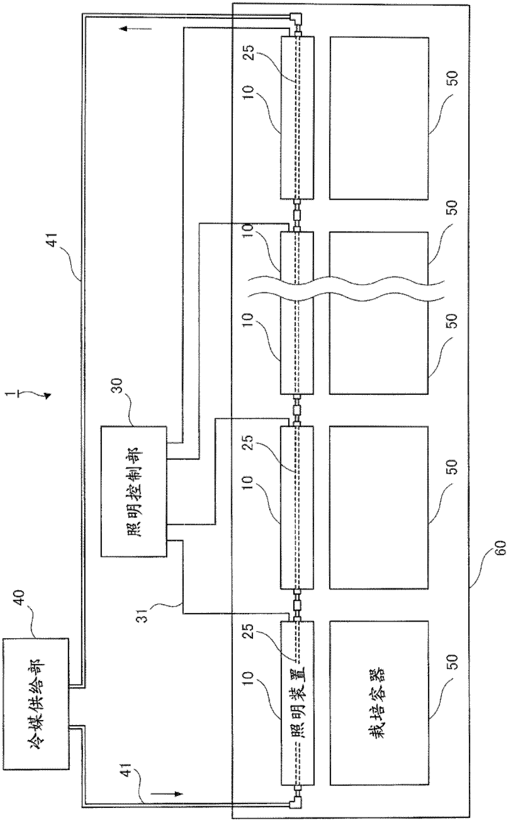
[0040] figure 1 It is a figure which shows an example of the plant cultivation system 1 to which this embodiment is applied.

[0041] The plant cultivation system 1 is equipped with a plurality of cultivation containers 50 and a plurality of lighting devices 10. The plurality of cultivation containers 50 are arranged in the cultivation chamber 60 to cultivate plants. 50 are placed close together to irradiate the cultivated plants with light. The lighting device 10 is provided with a refrigerant pipe 25 , respectively. Also, a plurality of lighting devices 10 are connected by a connection unit. That is, the refrigerant conduit 25 of a lighting device 10 is connected to the refrigerant conduit 25 (adjacent refrigerant conduit) of an adjacent lighting device 10 to form a refrigerant flow path.

[0042]In addition, the plant cultivation system 1 includes an illumination control unit 30 installed outside the cultivation room 60 to control on / off of the illumination of the illumi...

no. 2 Embodiment approach

[0189] In the first embodiment, the light-emitting element assembly 21 including the first semiconductor light-emitting element 64a emitting blue light and the second semiconductor light-emitting element 64b emitting red light is mounted on the circuit board 22, and the circuit board 22 is mounted on a heat sink. Substrate 24. In this method, the heat generated from the first semiconductor light emitting element 64a and the second semiconductor light emitting element 64b is transferred from the back surface of the circuit substrate 22 to the heat dissipation substrate 24 through the metal leads of the light emitting element assembly 21 and the through holes of the circuit substrate 22. .

[0190] Among them, the thickness of the metal leads of the light-emitting element assembly 21 is as thin as 0.15 mm, but the thermal resistance of the light-emitting element assembly 21 is not so low as 100° C. / W.

[0191] In this embodiment, in order to further improve the cooling efficien...


PUM


Abstract

An illuminating device (10) is provided with a casing configured from an outer cover (11) having a U shape, a transparent cover (12) provided so as to cover the opening of the U shape, a first side cover (13) provided on the left-hand side, and a second side cover (14) provided on the right-hand side. Further, the illuminating device (10) is provided with a light-emitting element package (21) mounted with a semiconductor light-emitting element in the casing, a circuit board (22) mounted with the light-emitting element package (21), a heat-dissipating base (24) to which the circuit board (22) is secured and which a coolant conduit (25) is provided in close contact with, a filmy insulating heat-dissipating member (23) for electrically insulating the circuit board (22) from the heat-dissipating base (24), and a reflector (26) for reflecting light. The inside of the casing is sealed. Therefore, the problems due to dew condensation and moisture absorption while the semiconductor light-emitting element is efficiently cooled by means of a coolant, such as water are solved, and an illuminating device for plant cultivation using the semiconductor light-emitting element, which has a long life and can maintain high efficiency, as the light source and a plant cultivation system using the same are provided.

Description

technical field [0001] The present invention relates to a lighting device for plant cultivation and a plant cultivation system using the lighting device for plant cultivation. Background technique [0002] In recent years, as an agricultural environment that is not affected by changes in natural conditions, plant factories and vegetable factories that control all conditions that affect plant growth such as light, temperature, humidity, and carbon dioxide concentration in the cultivation environment to produce crops have continued to be put into practical use. . [0003] Among these plant factories, there are plant factories of the complete artificial light type and the solar light combined type, both of which must be equipped with lighting devices for irradiating artificial light. Also, it is necessary to irradiate red and blue lights on the plants from the lighting device. As a light source of the lighting device, a semiconductor light emitting element (LED: Light Emittin...

Claims


Application Information

Patent Timeline
Patent Type & Authority Applications(China)
IPC IPC(8): A01G7/00F21V29/00F21V31/00
CPCF21Y2101/02A01G7/045F21Y2105/001F21V29/02H01L2224/48091H01L2224/48247H01L2224/48257H01L2224/45147F21Y2105/10F21Y2115/10H01L2224/45144A01G9/249H01L2924/00014H01L2924/00011F21V29/52F21V29/65
Inventor 安田刚规渡边博之
Owner SHOWA DENKO KK
Why Eureka
Try Eureka