Discharge mechanism of steel bar truss forming machine

A steel truss and forming machine technology, applied in metal processing and other directions, can solve the problems affecting the normal operation and detachment of the steel truss forming machine

Active Publication Date: 2012-04-25
浙江亿洲机械科技有限公司
View PDF6 Cites 5 Cited by
  • Summary
  • Abstract
  • Description
  • Claims
  • Application Information

AI Technical Summary

Problems solved by technology

[0002] Steel bar truss forming machine is a device used to manufacture steel bar trusses, which includes a feeding mechanism that releases the steel bars. The existing feeding mechanism includes a coil rack and a rotating column fixed on the lower side of the coil rack. The rotating column It is connected with the frame by rotation. When the steel bar truss forming machine is working, the steel bars on the coil rack are pulled out, and the pulling force makes the coil rack rotate through the rotating column, so that the steel bars are continuously ...

Method used


Image

  • Discharge mechanism of steel bar truss forming machine
  • Discharge mechanism of steel bar truss forming machine
  • Discharge mechanism of steel bar truss forming machine

Examples


Embodiment Construction

[0020] The present invention will be described in further detail below in conjunction with the accompanying drawings and specific embodiments.

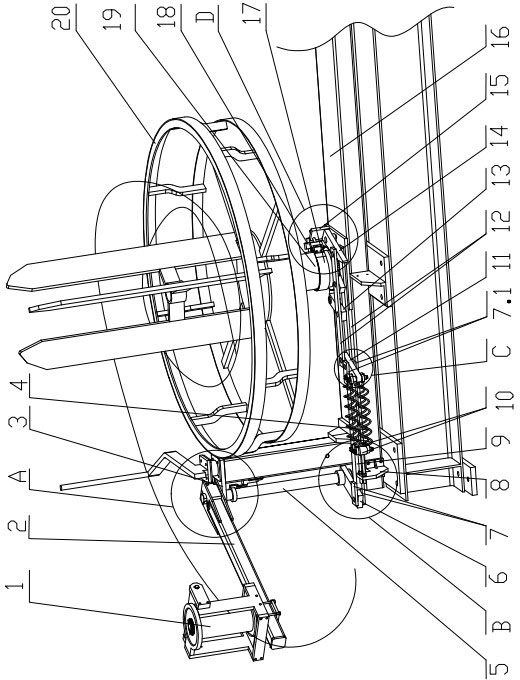
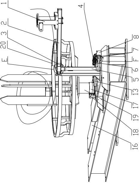
[0021] Depend on figure 1 As can be seen from the structural schematic diagram of the discharging mechanism of the steel bar truss forming machine of the present invention, it can be seen that it includes a coil rack 20, a steel bar output guide seat 1, a rotating column 19 arranged at the lower end of the coil rack 20, and the rotating column 19 is rotationally connected with the frame 16. Including the interlocking device that the steel bar output guide seat 1 outputs the steel bar to rotate or stop and the coil rack 20 rotates or stops; When exporting steel bars, the coil rack does not rotate.

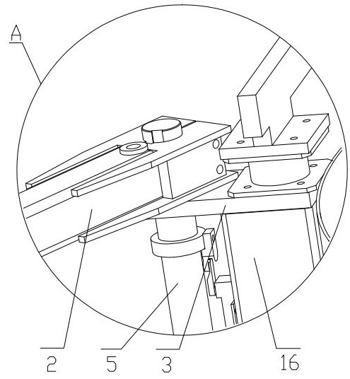
[0022] The linkage device includes a guide seat 1 for drawing steel bars, the guide seat 1 is fixed on one end of the rocker arm 2, the other end of the rocker arm 2 is hinged with the connecting rod seat 3 fixed on the frame 16, and the r...


PUM


Abstract

The invention discloses a discharge mechanism of a steel bar truss forming machine. The discharge mechanism comprises a perform rack (20), a steel bar output guide seat (1), a rotating column (19) which is arranged on the lower end of the perform rack (20), and a linkage device, wherein, the rotating column (19) is rotatably connected with a frame (16); and by means of the linkage device, the perform rack (20) rotates when the steel bar output guide seat (1) rotates when outputting steel bars, and the perform rack (20) stops when the steel bar output guide seat (1) stops outputting the steel bars. The discharge mechanism of the steel bar truss forming machine and the steel bars can stop and work synchronously, and the perform rack (20) does not rotate when the discharge mechanism does not work.

Description

technical field [0001] The invention relates to a mechanical structure, in particular to a feeding mechanism of a steel bar truss forming machine. Background technique [0002] Steel bar truss forming machine is a device used to manufacture steel bar trusses, which includes a feeding mechanism that releases the steel bars. The existing feeding mechanism includes a coil rack and a rotating column fixed on the lower side of the coil rack. The rotating column It is connected with the frame by rotation. When the steel bar truss forming machine is working, the steel bars on the coil rack are pulled out, and the pulling force makes the coil rack rotate through the rotating column, so that the steel bars are continuously pulled out. The existing discharging mechanism has some shortcomings. : When the steel bar truss forming machine stops working, the coil frame will not stop rotating immediately due to the inertia effect. The steel bar truss forming machine is working normally; wh...

Claims


Application Information

Patent Timeline
IPC IPC(8): B23Q7/00B21F23/00
Inventor 陈增光
Owner 浙江亿洲机械科技有限公司
Why Eureka
Try Eureka