
Electronic lock capable of being automatically locked

An automatic locking and electronic lock technology, applied in the field of electronic locks, can solve the problems of high energy consumption of electronic locks, reduce the safety and reliability of electronic locks, and the mechanical transmission part cannot realize automatic reset and lock, so as to improve safety and reliability, The effect of reducing energy consumption

Active Publication Date: 2012-04-25
NINGBO HI-TECH DISTRICT RUIAO OPTOELECTRONIC TECH CO LTD
View PDF6 Cites 14 Cited by
  • Summary
  • Abstract
  • Description
  • Claims
  • Application Information

AI Technical Summary

Problems solved by technology

[0003] The current electronic locks are generally composed of two parts: the electronic drive part and the mechanical transmission part. The drive of the electronic drive part drives the mechanical transmission part to realize the functions of unlocking and locking. The premise for the electronic drive part to work is to first give the electronic drive Partial power supply, many electronic locks set the power supply device in the lock cylinder, so that the lock cylinder of the electronic lock is always in a charged state, and because the unlocking and locking actions of the current mechanical transmission part need to be driven by the electronic drive part, resulting in electronic The energy consumption of the lock is large, and when the lock cylinder is in a power-off state, the mechanical transmission part cannot automatically reset and lock, thereby reducing the safety and reliability of the electronic lock.

Method used


Image

  • Electronic lock capable of being automatically locked
  • Electronic lock capable of being automatically locked
  • Electronic lock capable of being automatically locked

Examples


Embodiment Construction

[0022] The present invention will be further described in detail below in conjunction with the accompanying drawings and embodiments.

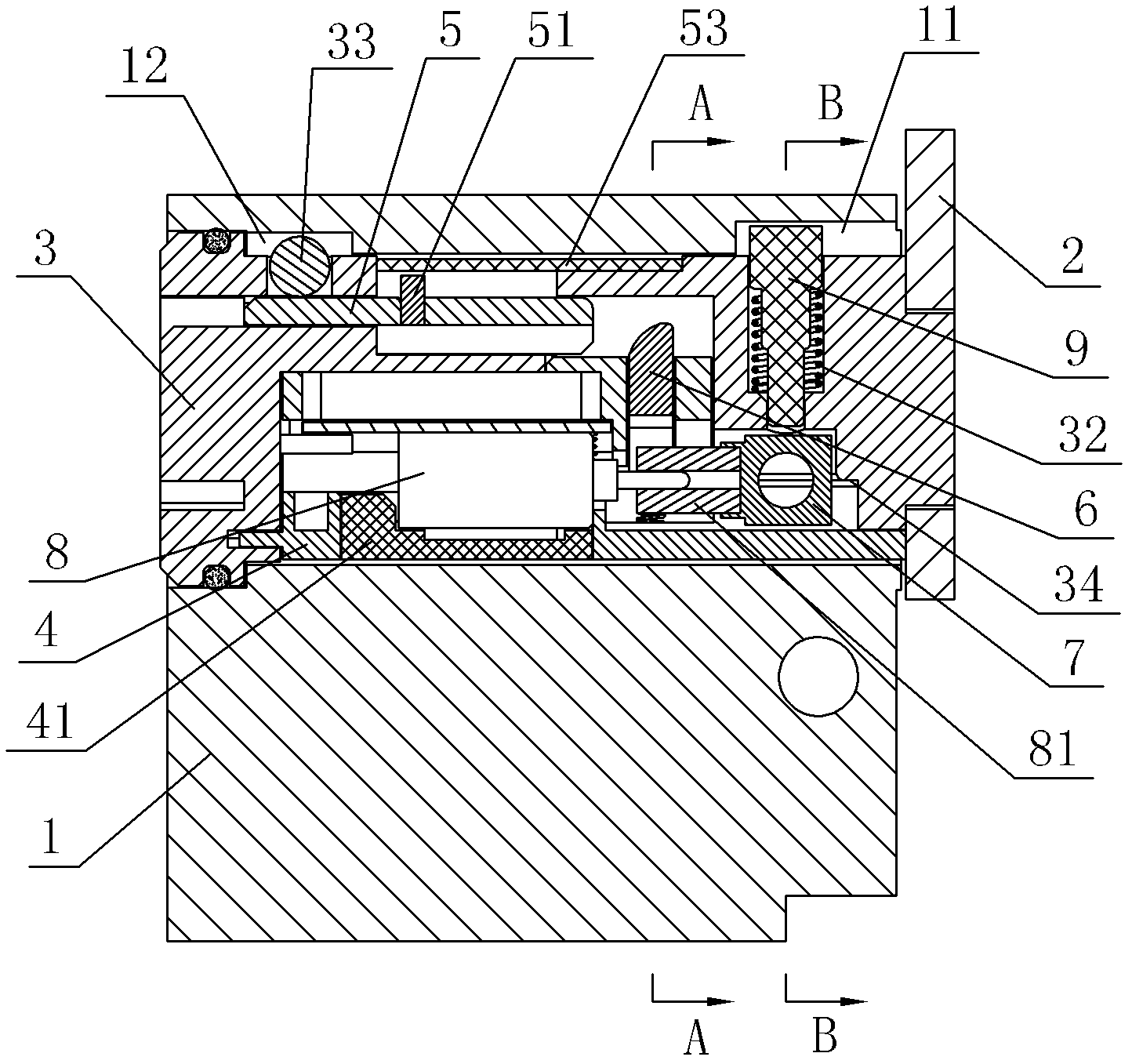
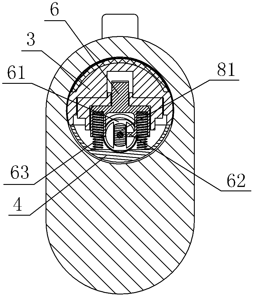
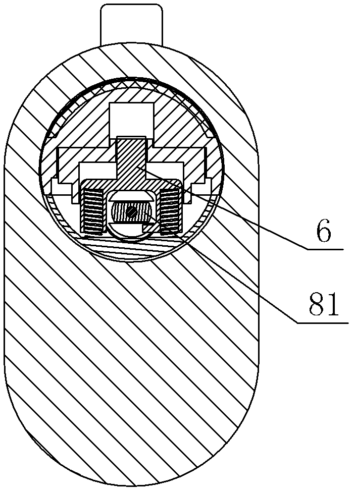
[0023] As shown in the figure, an electronic lock that can be automatically locked includes a lock case 1, a lock cylinder assembly and a plectrum 2. The lock cylinder assembly includes an electronic drive part and a mechanical transmission part. The mechanical transmission part includes a lock cylinder mounting base 3, Lock cylinder cover plate 4, drive block 5, push block 6 and limit post 7, drive block 5 horizontally slide and insert in the lock cylinder mounting seat 3, drive block 5 is clamped with reset block 51, reset block 51 and lock A first return spring 52 is connected between the core mounting seats 3, and a small cover plate 53 is covered on the first return spring 52, and the small cover plate 53 is crimped on the lock cylinder mounting seat 3, and the push block 6 is vertically slid and plugged in. In the lock cylinder mounting ...


PUM


Abstract

The invention discloses an electronic lock capable of being automatically locked, which comprises a lock shell, a lock core module and a shifting sheet, wherein the lock core module comprises an electronic drive part and a mechanical transmission part, and the electronic lock capable of being automatically locked is characterized in that: the mechanical transmission part comprises a lock core installation seat, a lock core cover plate, a drive block, a push block and a limiting column, the drive block is connected with a return block in a clamping way, a first return spring is arranged between the return block and the lock core installation seat, the electronic drive part comprises a motor, a drive shaft of the motor is fixedly provided with a square rotating shaft, the rotating shaft passes through the push block to be connected with the limiting column in a plugging way, the push block is provided with a mechanical return device, the front part of the lock core installation seat is provided with a vertical staircase through hole, a clamping pin is arranged inside the staircase through hole, a second return spring is arranged between the clamping pin and the staircase through hole, the limiting column is provided with a radial limiting hole, and the shifting sheet is sleeved on the front end part of the lock core installation seat. The electronic lock capable of being automatically locked has the advantages that: when the electronic drive part of the electronic lock stays at a power-off state, the entire electronic lock can be automatically reset to lock, so the safety and reliability of the electronic lock can be improved.

Description

technical field [0001] The invention relates to a lock, in particular to an electronic lock capable of automatic locking. Background technique [0002] Lock is requisite a kind of antitheft tool in people's life, adorn a lock on door and window, can prevent that thief enters house and steals. There are many types of existing locksets, such as mechanical locks, electronic locks and remote control electronic locks, etc. Different types of locksets have different structures and functions. [0003] The current electronic locks are generally composed of two parts: the electronic drive part and the mechanical transmission part. The drive of the electronic drive part drives the mechanical transmission part to realize the functions of unlocking and locking. The premise for the electronic drive part to work is to first give the electronic drive Partial power supply, many electronic locks set the power supply device in the lock cylinder, so that the lock cylinder of the electronic l...

Claims


Application Information

Patent Timeline
Patent Type & Authority Applications(China)
IPC IPC(8): E05B47/06
Inventor 秦涛裘宏辉闵炼夏光伟
Owner NINGBO HI-TECH DISTRICT RUIAO OPTOELECTRONIC TECH CO LTD
Learn More