
Infrared-ray oven

An infrared oven and infrared technology are applied in clothing, shoe parts, shoemaking machinery, etc., which can solve the problems of high equipment operating costs, large energy consumption losses, and inability to observe changes in shoes, etc., to reduce equipment operating costs, The effect of improving the utilization rate of heat energy

Inactive Publication Date: 2012-05-02
谭官勤
View PDF0 Cites 2 Cited by
  • Summary
  • Abstract
  • Description
  • Claims
  • Application Information

AI Technical Summary

Problems solved by technology

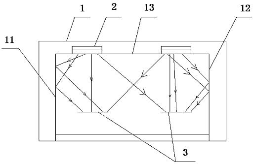
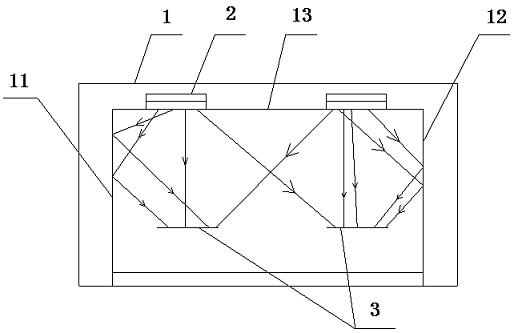
[0002] It is well known that infrared ovens are used in shoemaking production lines. Before the soles and uppers are bonded, the joints must be glued and then dried in an infrared oven. However, the left side of the infrared oven currently used 1. Both the right side plate and the upper side plate heat up under infrared heating and transfer the temperature to the wall side of the oven through the rack, resulting in large energy loss and high operating costs of the equipment; in addition, the box body of this oven is made of heat insulation Composed of insulating materials, and these materials are opaque, so this kind of oven can not observe the changes of the heated shoes inside. There is an observation port on the side wall of the oven, but these have certain limitations. Can't observe the inside of the box well

Method used


Image

  • Infrared-ray oven
  • Infrared-ray oven

Examples


Embodiment Construction

[0009] The present invention will be further described below in conjunction with accompanying drawing.

[0010] Such as figure 1 As shown, an infrared oven includes a box body 1, and an infrared heating device 2 is arranged on one of the side plates of the box body 1. In this embodiment, the infrared heating device 2 is an infrared lamp tube. The surface of at least one side plate of the box body 1 is provided with a reflective layer for reflecting infrared light. The reflective layer is a titanium plate, and the surface of the titanium plate can effectively reflect the infrared light emitted by the infrared lamp tube to the bottom of the shoe 3. sole or upper. In this embodiment, the upper side plate 13 of the box body 1 is provided with an infrared heating device 2, and the left side plate 11, the right side plate 12 and the upper side plate 13 of the box body are provided with a reflective layer for reflecting infrared rays. The front side panel of body 1 is a transparent...


PUM


Abstract

The invention discloses an infrared-ray oven, belonging to the oven field. The infrared-ray oven comprises a case, wherein one side plate of the case is provided with an infrared ray heating device; a reflecting layer for reflecting the infrared light is arranged on the surface of at least one side plate of the case; and at least one side plate of the case is a transparent vacuum segregation board. After using the structure, heat energy using rate is improved and device running cost is reduced in such a manner that at least one side plate of the oven case is provided with the reflecting layer; and at least one side plate of the case is a transparent vacuum segregation board, so users can conveniently and fully observe the variation of heated objects during the heating process in the case.

Description

technical field [0001] The invention relates to an oven, in particular to an infrared oven. Background technique [0002] It is well known that infrared ovens are used in shoemaking production lines. Before the soles and uppers are bonded, the joints must be glued and then dried in an infrared oven. However, the left side of the infrared oven currently used 1. Both the right side plate and the upper side plate heat up under infrared heating and transfer the temperature to the wall side of the oven through the rack, resulting in large energy loss and high operating costs of the equipment; in addition, the box body of this oven is made of heat insulation Composed of insulating materials, and these materials are opaque, so this kind of oven can not observe the changes of the heated shoes inside. There is an observation port on the side wall of the oven, but these have certain limitations. Neither can observe the inside of the box well. Contents of the invention [0003] The...

Claims


Application Information

Patent Timeline
Patent Type & Authority Applications(China)
IPC IPC(8): A43D25/20
Inventor 谭官勤
Owner 谭官勤
Learn More