Punching machine

A punching machine and frame technology, applied in punching tools, metal processing, metal processing equipment, etc., can solve the problems of reducing punching speed, easy damage of punching machines, and difficulty in ensuring punching quality, so as to ensure punching. Quality, unbreakable effect

Inactive Publication Date: 2012-05-02
常州中翔机械制造有限公司
View PDF0 Cites 0 Cited by
  • Summary
  • Abstract
  • Description
  • Claims
  • Application Information

AI Technical Summary

Problems solved by technology

The problem with this punching machine is that because the upper template and the punch only move under the drive of the piston rod without other guide devices, the upper template and the punch sometimes deviate from the axis of the piston rod when they move up and down, making it difficult to guarantee the punching. The quality of the hole also reduces the punching speed, and the punching machine is also easy to damage

Method used


Image

  • Punching machine
  • Punching machine
  • Punching machine

Examples


Embodiment Construction

[0011] The present technology will be further described below through the embodiments in conjunction with the accompanying drawings.

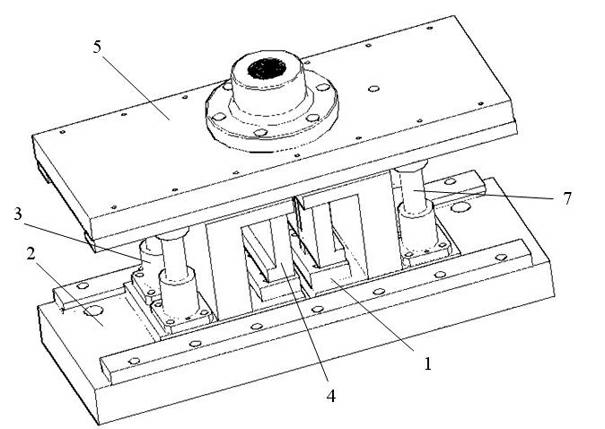
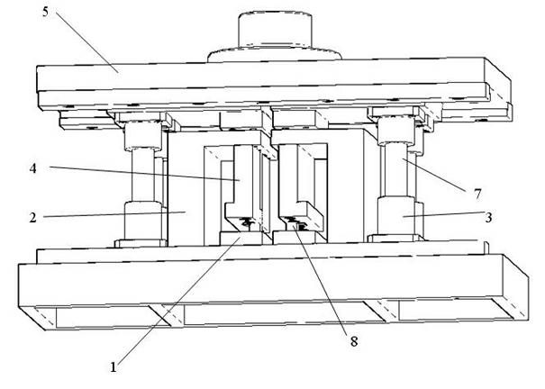
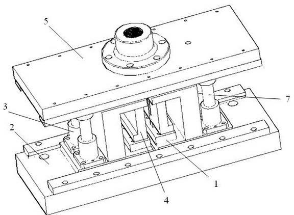
[0012] Such as figure 1 , 2 In the shown punching machine, two dies 1, two punch sleeves 4 and four guide sleeves 3 are all fixed on the frame 2. The upper end of the upper template 5 is connected with the piston rod of an oil cylinder or an air cylinder that drives it to move up and down. The lower part of the upper template 5 is connected with four guide pillars 7 extending into the guide sleeve and two punches 8 corresponding to the die through the punch sleeve. The guide post 7 and the guide sleeve 3 form an up and down sliding pair; the punch 8 and the punch sleeve 4 form an up and down sliding pair.


PUM


Abstract

The technology provides a punching machine. The punching head of the punching machine can move up and down linearly; and the punching machine can punch qualified holes at a high punching speed, and is not easy to damage. The punching machine comprises a machine frame, a female die which is fixed on the machine frame, and an upper template which can move up and down relative to the machine frame; the punching head corresponding to the female die is fixed to the upper template; the upper template is connected with the machine frame in an up-and-down sliding way through a guide post-guide sleeve pair; a punching head sleeve which plays a role in guiding the up-and-down movement of the punching head is fixed to the machine frame; and the punching head passes through the punching head sleeve.

Description

technical field [0001] This technology relates to punching machines. Background technique [0002] The existing punching machine comprises a frame, a die fixed on the frame, an upper template that moves up and down relative to the frame, and a punch corresponding to the die is fixed on the upper template. Its oil cylinders or air cylinders that move up and down are connected. Driven by the oil cylinder or air cylinder, the upper platen drives the punch to move up and down relative to the die, so as to punch out the required holes on the workpiece located between the punch and the die. The problem with this punching machine is that since the upper template and the punch only move under the drive of the piston rod without other guide devices, the upper template and the punch sometimes deviate from the axis of the piston rod when they move up and down, making it difficult to guarantee the punching force. The quality of the hole also reduces the punching speed, and the punchin...

Claims


Application Information

Patent Timeline
IPC IPC(8): B26F1/02B26F1/14B21D28/34
Inventor 仲志军
Owner 常州中翔机械制造有限公司
Why Eureka
Try Eureka