

Punching device for paper processing based on rolling wheel pre-pressing technology
A punching device and pre-compression technology, applied in metal processing and other directions, can solve the problems of poor punching effect, easy damage to paper products, and difficulty in meeting production requirements, and achieve the effect of preventing clogging of punching and ensuring punching quality.
- Summary
- Abstract
- Description
- Claims
- Application Information
AI Technical Summary
Problems solved by technology
Method used
Image

Examples
Embodiment 1
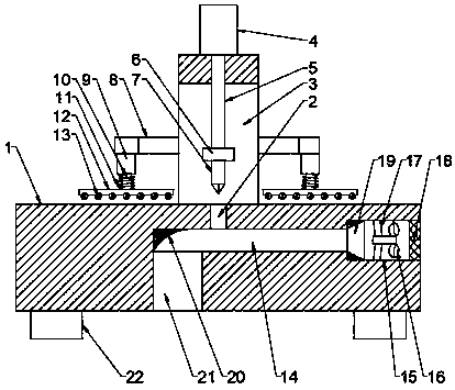
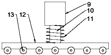
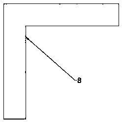
[0029] see Figure 1~3 , a punching device for paper product processing based on roller pre-compression technology, comprising a base 1, a punching hole 2 and a stand 3 are arranged in the middle of the top surface of the base 1, and the stand 3 is arranged on the punching hole 2 The rear side of the stand 3 is an L-shaped structure, the top of the stand 3 is provided with a hydraulic cylinder 4, and the bottom end of the telescopic rod 5 on the hydraulic cylinder 4 runs through the top wall of the stand 3 and is fixedly connected with a punching hole. 2 matched punches 7, the telescopic rod 5 and the stand 3 are slidingly connected, and the top end of the outer circular surface of the punch 7 is provided with a limit plate 6 matched with the punching hole 2 to start the hydraulic pressure Cylinder 4, use telescopic rod 5 to lower punch 7, use the mutual cooperation between punch 7 and punching hole 2, can realize the punching process on the support plate, and by setting limit...
Embodiment 2
[0032] This embodiment is a further elaboration on the basis of Embodiment 1. The base 1 is provided with a sewage discharge chamber 14 matched with the punching hole 2. The sewage discharge chamber 14 is connected through the punching hole 2. The sewage discharge chamber The right end of 4 is connected to the air intake hole 15 through, the left end of the inner cavity of the air intake hole 15 is provided with an air guide bucket 19 matched with the sewage chamber 14, and an air suction fan 16 is arranged in the air intake hole 15, The outside of described air intake fan 16 is evenly provided with some support rods 17, and air suction fan 16 is fixedly connected on the inner hole wall of air inlet 15 by support rod 17, and the right side end of described air inlet 15 is provided with Protective net 18, the left side of the inner cavity bottom wall of the sewage discharge chamber 14 is connected to the sewage discharge hole 21, and the inner cavity left side wall of the sewage...
PUM
 Abstract
Description
Claims
Application Information