Modular plug

A crystal head and main body technology, applied in the direction of electrical components, coupling devices, circuits, etc., can solve the problem of damage to the wire crimping part of the crystal head, and achieve the effect of reducing the damage caused by the wire crimping part and reducing the possibility

Inactive Publication Date: 2012-05-02
BUFFALO CORP LTD
View PDF4 Cites 8 Cited by
  • Summary
  • Abstract
  • Description
  • Claims
  • Application Information

AI Technical Summary

Problems solved by technology

[0008] However, in the plug structure described in Patent Document 1, when the plug is intended to be pulled out from the modular socket, the user holds the cable to pull out the plug.
In the case of repeating this operation, it may cause damage to the wire crimping part in the crystal head

Method used


Image

  • Modular plug
  • Modular plug
  • Modular plug

Examples


Embodiment Construction

[0027] Embodiments of the present invention will be described with reference to the drawings. In the drawings of the following embodiments, the same or similar reference numerals are given to the same or similar parts.

[0028] (1) The overall structure of the modular connector

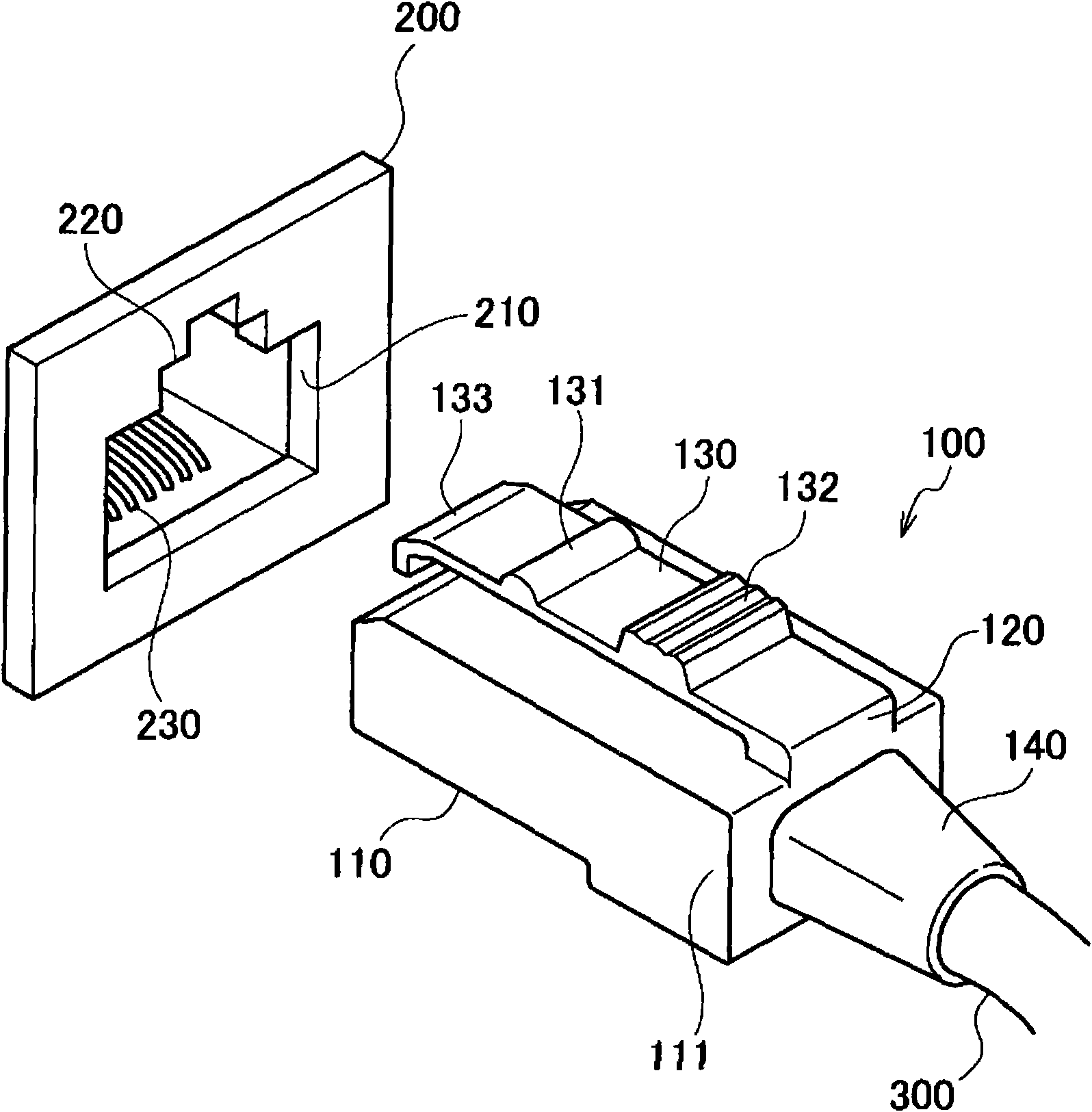
[0029] figure 1 It is a perspective view showing the overall structure of the modular connector of this embodiment.

[0030] Such as figure 1 As shown, the modular connector of this embodiment is composed of a modular socket 200 and a plug 100 inserted into the modular socket 200 .

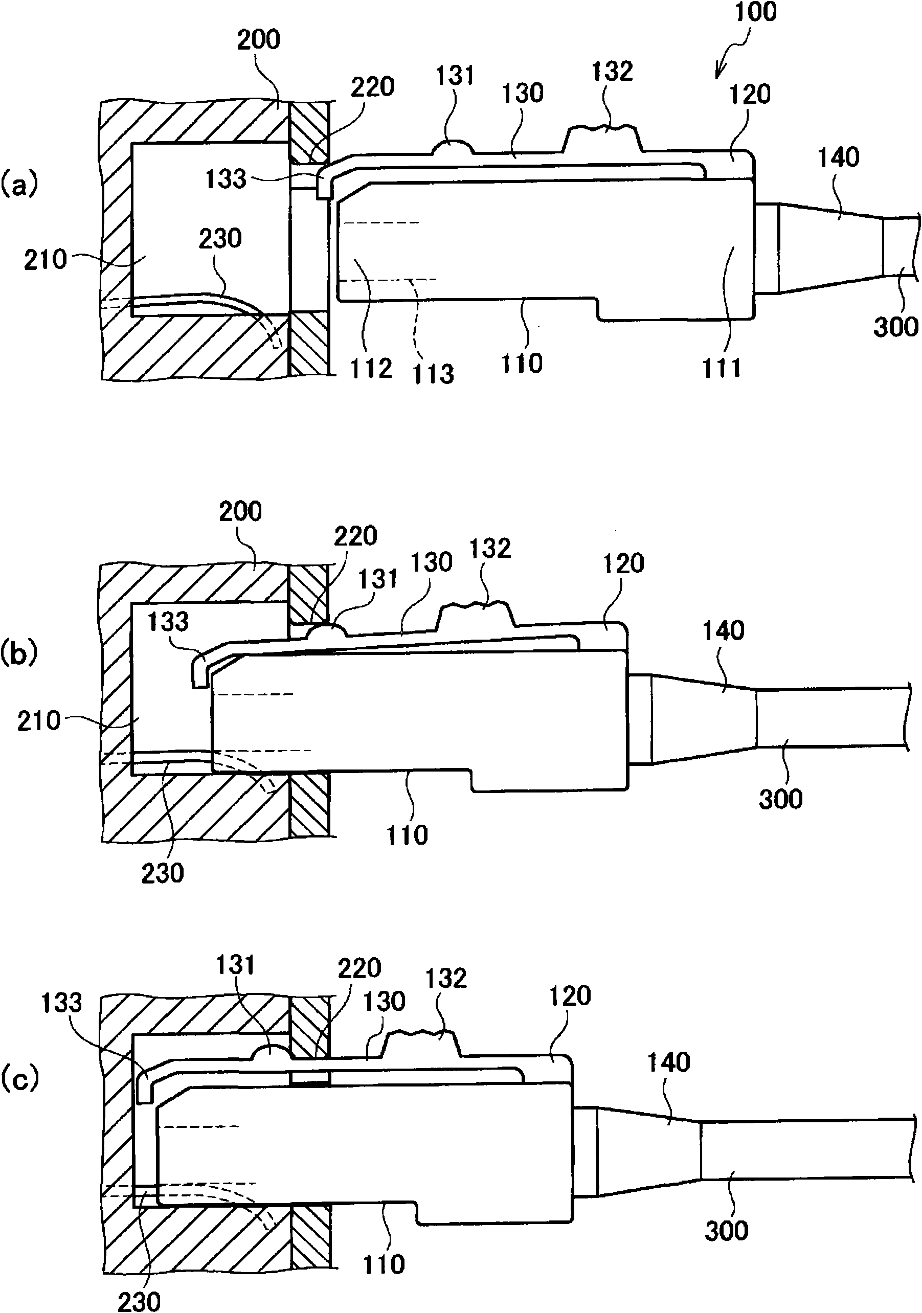
[0031] The modular jack 200 is installed on devices such as telephones and LAN devices. The modular socket 200 has an opening 210 into which the plug 100 is inserted. At the bottom of the opening 210, a terminal 113 connected to the crystal head 100 (refer to figure 2 (a)) The terminals 230 are electrically connected. A notch 220 is provided at an upper portion of the opening portion 210 . In addition, in this ...


PUM


Abstract

The invention provides a modular plug, which can be released from a locking state through being exerted with a force in the pulling direction and can reduce the damage possibility of a conductor crimping portion. The modular plug (100) capable of being inserted into a modularizied socket (200) or being pulled out of the modularizied socket (200) comprises a modular plug body (110), a supporting part (120), a rod (130) and a clamping protrusion (131). The supporting part (120) is arranged at the rear end (111) of the modular plug body (110). The rod (130) and the modular plug body (110) extend along the insertion direction with a gap reserved therebetween and can perform an elastic deformation with the supporting part (120) as the fulcrum thereof. The clamping projection (131) is arranged on the rod (130) and positioned more close to the insertion direction than the supporting part (120). The clamping projection (131) is engaged with the slot (220) of the modularizied socket (200).

Description

technical field [0001] The invention relates to a modular connector, in particular to a modular plug inserted into a modular jack. Background technique [0002] Conventionally, modular connectors have been widely used when connecting devices and cables such as telephones and LAN (Local Area Network) devices. The modular connector consists of a modular socket set on the device and a crystal head connected to the end of the cable. [0003] The crystal head has a crystal head body and a rod extending obliquely upward and rearward from the front end of the crystal head body. In addition, the insertion direction of the plug is referred to as "front", the direction of pulling out the plug is referred to as "rear", the side where the rod is provided is referred to as "upper", and the side where the rod is not provided (designated The side with terminals) is referred to as "underside". [0004] The rod is provided with a fixing claw that engages with the notch of the modular sock...

Claims


Application Information

Patent Timeline
IPC IPC(8): H01R13/629H01R13/639
Inventor 石彻白敬
Owner BUFFALO CORP LTD
Why Eureka
Try Eureka