Welding wire feeding device

A technology of feeding device and welding wire, applied in welding equipment, welding accessories, arc welding equipment, etc., can solve problems such as troublesome replacement operations, and achieve the effect of simplifying replacement operations

Inactive Publication Date: 2012-05-09
DAIHEN CORP
View PDF11 Cites 5 Cited by
  • Summary
  • Abstract
  • Description
  • Claims
  • Application Information

AI Technical Summary

Problems solved by technology

[0009] In order to remove the wire guide 5, it is necessary to remove the feed reel 10 etc. as above, and the replacement work is troublesome.

Method used


Image

  • Welding wire feeding device
  • Welding wire feeding device
  • Welding wire feeding device

Examples


Embodiment approach 1

[0073] Embodiments of the invention will be described based on examples with reference to the drawings.

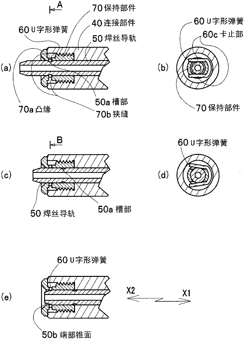
[0074] figure 1 (a) is a partial sectional view of the wire feeding device according to Embodiment 1 of the present invention. figure 1 (b) is figure 1 (a) A cross-sectional view. figure 1 (c), (d), and (e) are diagrams showing the operating state of Embodiment 1 of the present invention, figure 1 (d) is figure 1 (c) B-direction cross-sectional view.

[0075] The difference between the wire guide 50 of the wire feeder according to Embodiment 1 of the present invention and the wire guide 50 of the conventional wire feeder is as follows.

[0076] exist figure 1 In (a), (c), and (e), it is assumed that the wire feeding direction is the X1 direction, and the opposite direction is the X2 direction. An internal thread is provided on the inner diameter of the end portion of the connecting member 40 on the feeding drum 10 side (X2 direction). The holding member 70 i...

Embodiment approach 2

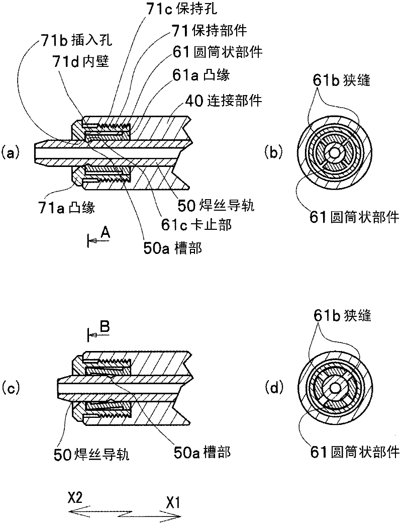
[0086] figure 2 (a) is a partial cross-sectional view of a welding wire feeding device according to Embodiment 2 of the present invention, figure 2 (b) is figure 2 (a) A cross-sectional view. figure 2 (c), (d) are figures which show the operation state of Embodiment 2 of this invention, figure 2 (d) is figure 2 (c) B-direction cross-sectional view. exist figure 2 In (a) and (c), it is assumed that the wire feeding direction is the X1 direction, and the opposite direction is the X2 direction. An internal thread is provided on the inner diameter of the end portion of the connecting member 40 on the feeding drum 10 side (X2 direction). The holding member 71 is a cylindrical member, and an external thread screwed into the internal thread of the connecting member 40 is provided on the outer peripheral portion of the front end (X1 direction), and a flange 71a is provided at the other end (X2 direction), and the end surface of the flange 71a is It abuts against the end ...

Embodiment approach 3

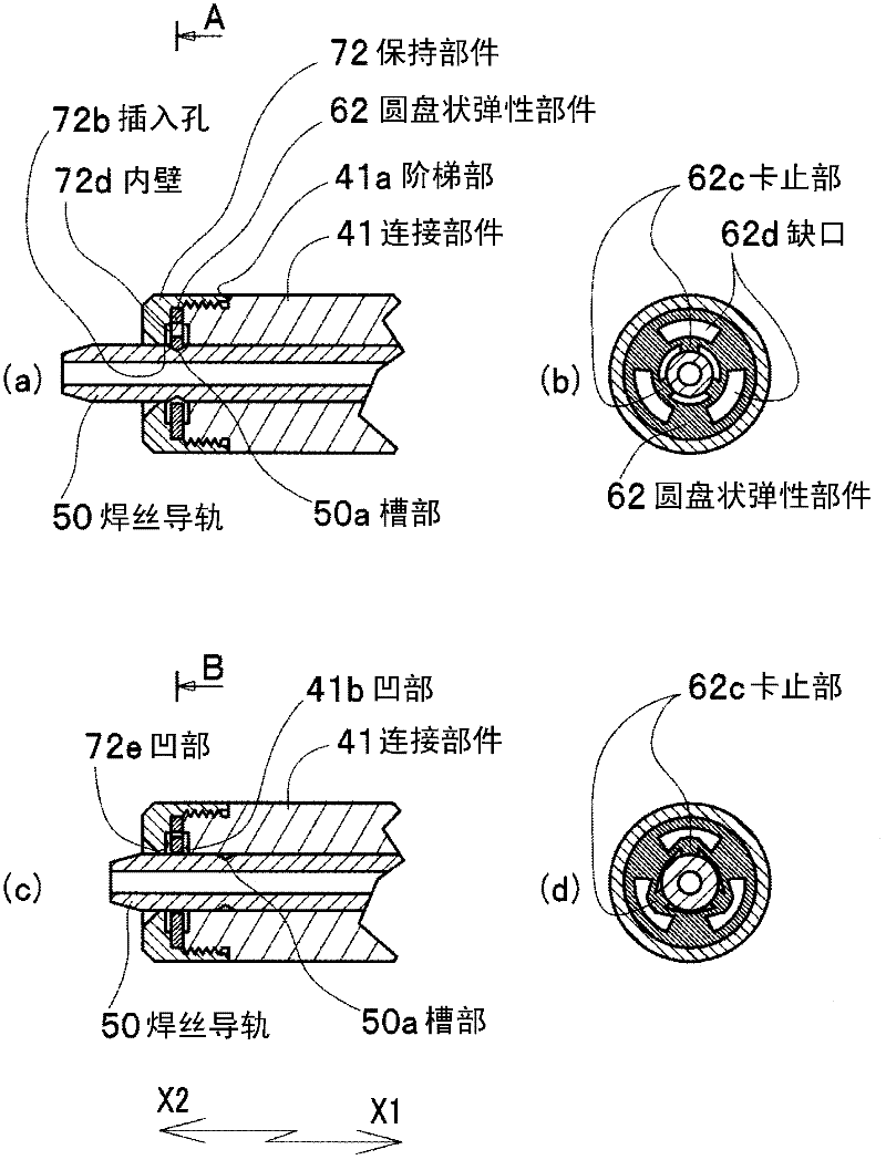
[0093] image 3 (a) is a partial cross-sectional view of a welding wire feeding device according to Embodiment 3 of the present invention, image 3 (b) is image 3 (a) A cross-sectional view. image 3 (c), (d) are figures which show the operation state of Embodiment 3 of this invention, image 3 (d) is image 3 (c) B-direction cross-sectional view. exist image 3 In (a) and (c), it is assumed that the wire feeding direction is the X1 direction, and the opposite direction is the X2 direction.

[0094] The outer diameter of the end portion of the connecting member 41 on the feeding drum 10 side (X2 direction) is provided with an external thread, and a stepped portion 41a is formed from the end of the external thread to the outer peripheral portion. The holding member 72 is a cylindrical member, and an internal thread screwed into the external thread of the connection member 41 is provided on the inner diameter portion of the front end (X1 direction), and the front end (X1 ...


PUM


Abstract

The present invention provides a welding wire feeding device (1) which can simplify change operation of a welding wire passage component that is equipped between a feeding reel (10) and pipeline (2) and feeds the welding wire (3) to the pipeline (2), namely a welding wire guide rail (50). For this purpose, a slot part (50a) is equipped at an outer peripheral surface at an end of the feeding reel (10) of the welding wire guide rail (50). Because a fixing component (60) which inserts a stopping part (60c) that elastically reduces diameter in a diameter direction of the welding wire guide rail (50) into the slot part (50a) for fixing the welding wire guide rail is provided, fixing of a slot part (50b) is released through pressing down an end face at the side of the feeding reel (10) of the welding wire guide rail (50) in the welding wire feeding direction oppositely to the elastic force of the fixing component (60) when the welding wire guide rail (50) is replaced, thereby releasing fixing of the slot part (50b). Therefore the welding wire guide rail (50) can be detached.

Description

technical field [0001] This invention relates to improvements in welding wire feeders. Background technique [0002] In molten electrode arc welding, a wire feeding device is used in order to feed the welding wire stably. (For example, refer to Patent Document 1.) In the prior art, as this welding wire feeding device, Figure 4 The device shown is widely used. Figure 4 It is a partial sectional view showing the structure of a conventional welding wire feeding device. In this figure, a wire feeder 1 is equipped with a feed motor (not shown), and a feed reel 10 is attached to a motor shaft of the feed motor by a feed reel attachment screw 11 . [0003] A pressure roll 12 is disposed opposite to the feed roll 10 . The pressure reel 12 is attached substantially at the center of the pressure reel holding member 13 , and the base end portion of the pressure reel holding member 13 is rotatably attached to the wire feeder main body. The pressurizing force adjusting mechanism 14 ...

Claims


Application Information

Patent Timeline
Patent Type & Authority Applications(China)
IPC IPC(8): B23K9/133B23K9/32
Inventor 清水文夫
Owner DAIHEN CORP
Why Eureka
Try Eureka