Screen printing device and screen printing method

A technology of screen printing machine and paste, which is applied in the direction of screen printing machine, printing, printing machine, etc.

Active Publication Date: 2013-08-28
PANASONIC INTELLECTUAL PROPERTY MANAGEMENT CO LTD
View PDF10 Cites 5 Cited by
  • Summary
  • Abstract
  • Description
  • Claims
  • Application Information

AI Technical Summary

Problems solved by technology

Cartridge replacement by opening the upper part

Method used


Image

  • Screen printing device and screen printing method
  • Screen printing device and screen printing method
  • Screen printing device and screen printing method

Examples


Embodiment Construction

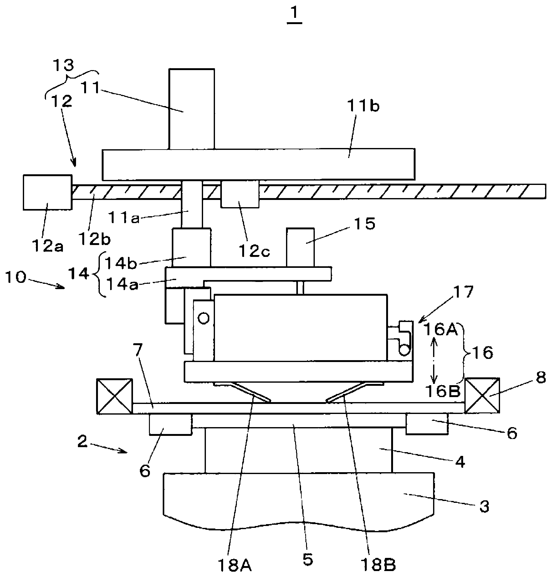
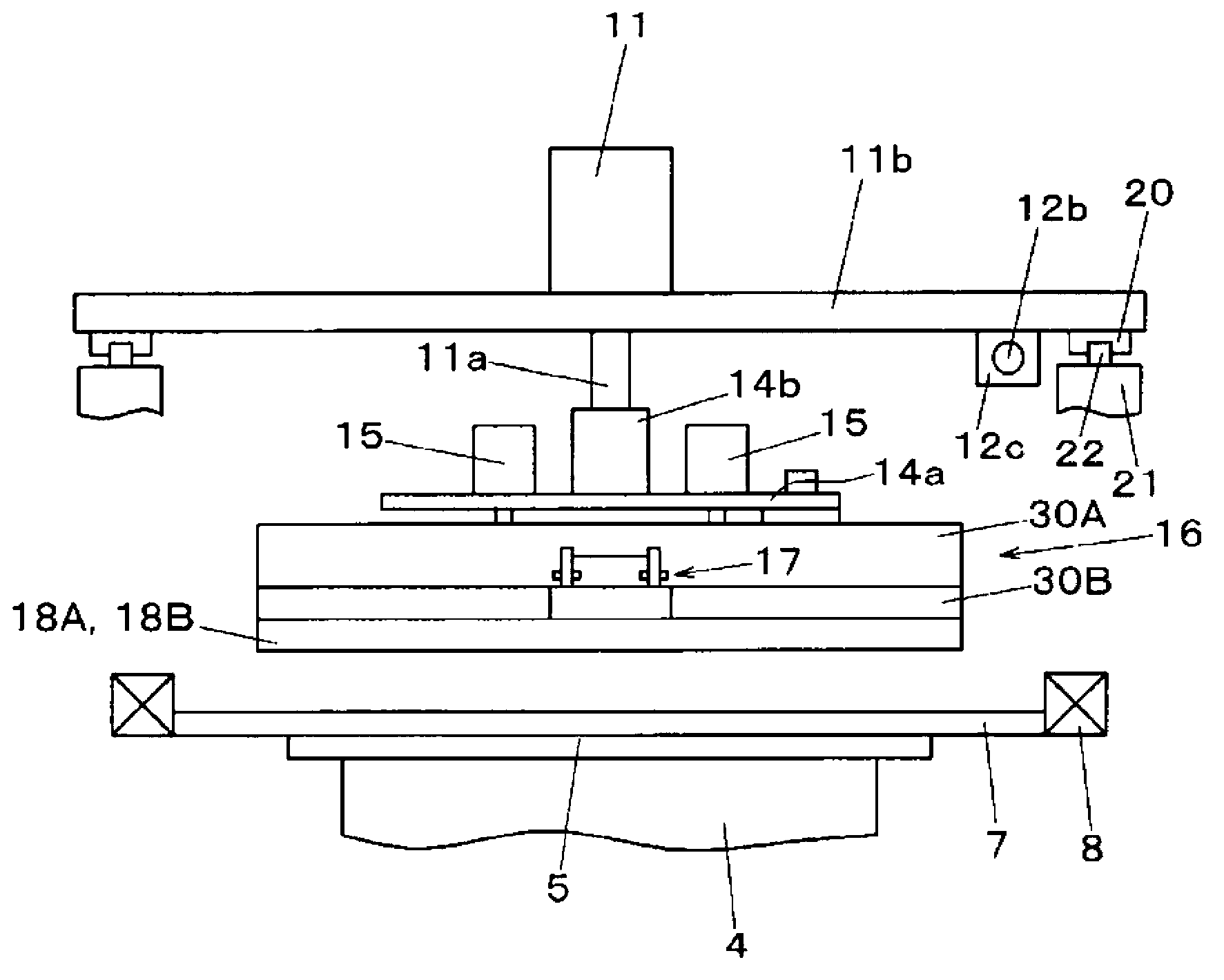
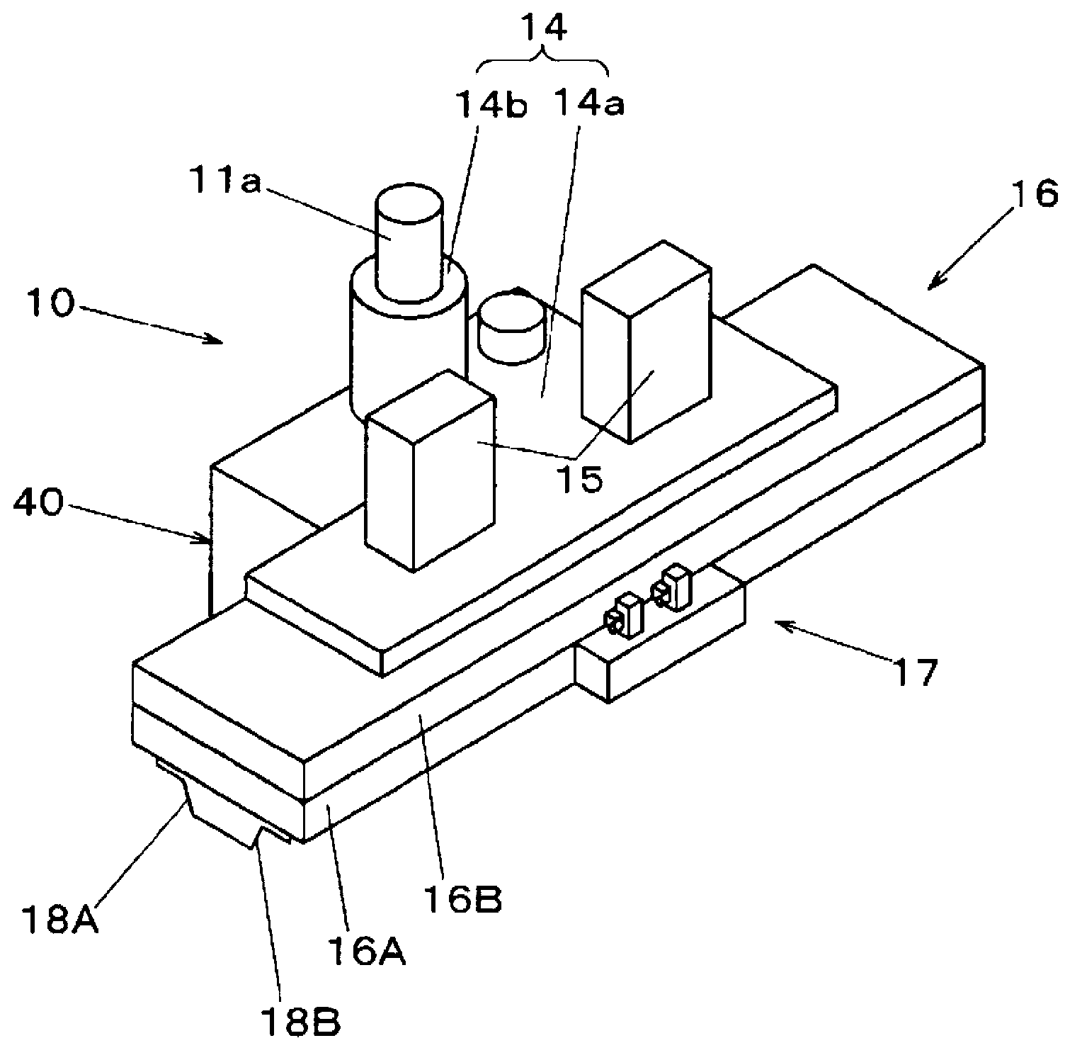
[0024] The embodiments of the present invention will now be described with reference to the drawings. First refer to figure 1 , 2 And 3 describe the entire configuration of the screen printer 1. The screen printer 1 has the following functions. That is, the squeegee head 10 slides on the mask plate 7 under the action of the head drive mechanism 13, so that the substrate 5 is printed with the solder paste 9 as an electronic component bonding paste through the pattern hole 7a of the mask plate 7. in figure 1 with 2 Among them, the screen printer 1 is configured such that the mask plate 7 held by the mask holder 8 is set at a raised position above the substrate positioning portion 2 and the screen printing mechanism is also located above the mask plate 7.

[0025] The structure of the substrate positioning portion 2 is described. The lower substrate receiver 4 is provided on the upper surface of the moving table 3 so as to be able to perform ascending and descending actions. The ...


PUM


Abstract

A holder mechanism (40) is configured from a shaft bracket (44) that is joined to a linking part and has a vertical rotation axis (44a); a shaft member (45), which extends in the horizontal direction from the shaft bracket (44) and rotates freely around the rotation axis (44a); and an interdigitating part (36) formed on a squeegee unit (16) and into which the shaft member (45) fits detachably. As a result, it is possible to attach and detach the entire squeegee unit (16) by moving the squeegee unit (16) only in the horizontal direction.

Description

Technical field [0001] The present invention relates to a screen printing machine and a screen printing method for printing a substrate with paste, such as solder paste and conductive paste. Background technique [0002] So far, in the electronic component mounting step, a method using a closed squeegee head has been known as a screen printing method for printing a substrate with paste (for example, solder paste and conductive paste). In this method, unlike the conventional screen printing in which the paste is directly supplied above the mask, the paste in the squeegee head is pressurized while keeping the squeegee head in which the paste is stored in contact with the mask. Thus, the paste is squeezed into the pattern hole of the mask plate through the paste contact surface provided on the lower surface of the squeegee head. Then, the squeegee head slides on the mask plate so that each pattern hole is sequentially filled with paste (see, for example, Patent Document 1). In the...

Claims


Application Information

Patent Timeline
Patent Type & Authority Applications(China)
IPC IPC(8): B41F15/40B41F15/08H05K3/12H05K3/34
CPCB41F15/42H05K3/1233H05K3/3485B41F15/08B41F15/40H05K3/12H05K3/34B41F15/44
Inventor 内田英树堀江勋矢泽隆
Owner PANASONIC INTELLECTUAL PROPERTY MANAGEMENT CO LTD
Why Eureka
Try Eureka