Urea Water Tank for Construction Machine

a construction machine and water tank technology, applied in machines/engines, separation processes, filtration separation, etc., can solve the problems of cost increase and workability degradation, and achieve the effect of simple configuration and easy replacement of filter parts

Active Publication Date: 2021-07-22
NIHON KENKI CO LTD
View PDF0 Cites 5 Cited by
  • Summary
  • Abstract
  • Description
  • Claims
  • Application Information

AI Technical Summary

Benefits of technology

[0009]According to the present invention, the filter can be disposed in a simple configuration and the replacement work of the filter can be easily performed.

Problems solved by technology

As a result, there is posed a problem of inviting degradation of workability and an increase in cost at the time of assembling the urea water tank.
In addition, there is a possibility that the bag shaped filter comes into contact with various kinds of sensors during the replacement work of the filter.
Therefore, there is a problem that at the replacement working time it is necessary to work in a careful way not to damage the sensors, taking time for the replacement work of the filter.

Method used


Image

  • Urea Water Tank for Construction Machine
  • Urea Water Tank for Construction Machine
  • Urea Water Tank for Construction Machine

Examples


first embodiment

[0064]The urea water tank 11 has the configuration as described above, and next, an explanation will be made of an example of the working procedure in a case of assembling the urea water tank 11.

[0065]First, descriptions will be made of a case of mounting the sensor unit 20 on the sensor mounting member 16. The upper end sides of the level sensor 21, the heater 22, the supply line 23, the return line and the like are inserted in the respective insertion holes 19B of the cap body 19, which is made to be in a state of being held by a resilient force. In this state, the tubular part 17A of the mounting tubular body 17 is fitted in the annular groove 19A of the cap body 19. Thereby, the sensor mounting member 16 and the sensor unit 20 can be formed as one subassembly.

[0066]On the other hand, at the tank body 12-side the filter tubular part 24A of the filter 24 is inserted in the unit insertion opening 12H of the tank body 12 from the lower end 24A4-side. Thereby, the lower end 24A4 of ...

second embodiment

[0079]In FIG. 9, a urea water tank 31 includes the sensor mounting member 16 and the sensor unit 20 that are described above, and a tank body 32, a closing bottom plate 36 and a filter 38 that will be described later.

[0080]The tank body 32 according to the second embodiment is, as substantially similar to the tank body 12 according to the first embodiment, formed of a top surface part 32A having a flat surface 32A1 and an inclined surface 32A2, a bottom surface part 32B, a front surface part 32C, a rear surface part 32D, a left surface part 32E and a right surface part (not shown). The inclined surface 32A2 of the top surface part 32A is provided with a water supply port 32F with a cap 32F1.

[0081]As shown in FIG. 10, the flat surface 32A1 of the top surface part 32A is provided with a unit insertion opening 32G. The unit insertion opening 32G is an opening for insertion of the sensor unit 20 and acts also as a fitting part in which an upper end 38A4 of a filter tubular part 38A in ...

third embodiment

[0108]However, the present invention is not limited to these configurations. That is, the present invention may be configured such that the unit insertion opening as the opening is disposed on the bottom surface part of the tank body only, and both of the sensor unit and the filter are inserted upward from the unit insertion opening. Further, this arrangement may be likewise applied to the third embodiment as well. In this case, the filter integral type mounting member 41 and the sensor unit 20 may be inserted upward from the unit insertion opening as the opening disposed on the bottom surface part of the tank body only.

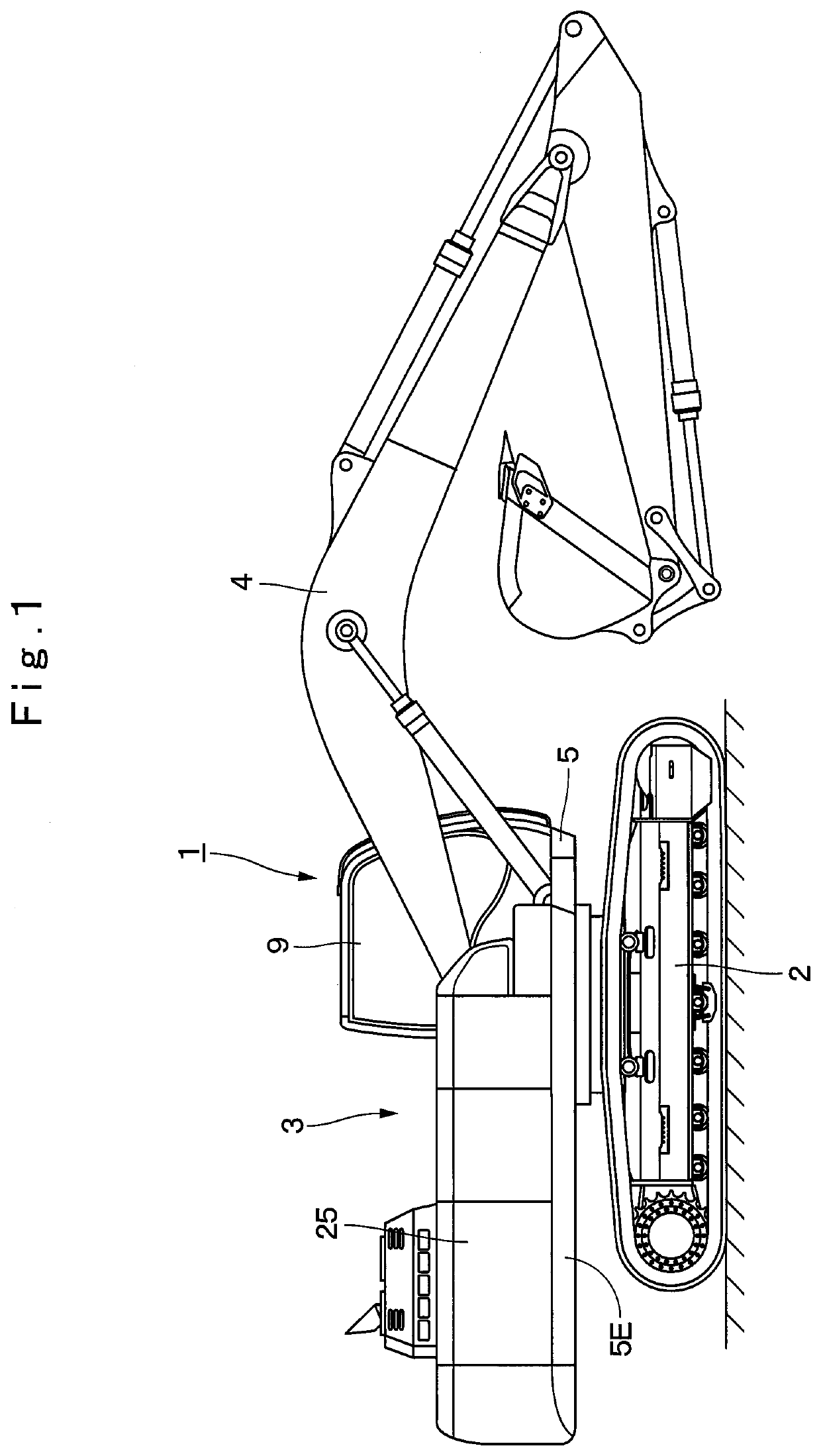
[0109]Each of the embodiments is explained by taking the urea water tank 11 or 13 of the hydraulic excavator 1 of the crawler type as an example. However, the present invention is not limited thereto, and may be applied widely to urea water tanks disposed in other construction machines such as a wheel type hydraulic excavator, a hydraulic crane, a wheel loader and th...


PUM

PropertyMeasurementUnit
dimensionaaaaaaaaaa
resilientaaaaaaaaaa
shapeaaaaaaaaaa

Abstract

A urea water tank (11) is provided with a unit insertion opening (12H) that is disposed on a top surface part (12A) of a tank body (12) and opens more largely than an external dimension (D2) of a sensor unit (20), a sensor mounting member (16) that is disposed on the top surface part (12A) of the tank body (12) and closes the unit insertion opening (12H), and a filter which is formed as a tubular body to surround the sensor unit (20), and inserted in the unit insertion opening (12H) of the tank body (12) from a lower end (24A4)-side, and having an upper end (24A3) mounted on the top surface part (12A) of the tank body (12) by using the sensor mounting member (16).

Description

TECHNICAL FIELD[0001]The present invention relates to a urea water tank for a construction machine disposed in a hydraulic excavator or the like for reserving urea water that is supplied to an exhaust gas post-treatment device, for example.BACKGROUND ART[0002]In general, a hydraulic excavator as a representative example of construction machines is configured with an automotive lower traveling structure, an upper revolving structure that is mounted on the lower traveling structure to be capable of revolving thereon and a front device that is mounted on a front side of the upper revolving structure to be capable of tilting and lifting thereto.[0003]The upper revolving structure includes a revolving frame forming a support structure, an engine mounted on the revolving frame, an exhaust gas post-treatment device that is connected to an exhaust side of the engine to purify an exhaust gas discharged from the engine and a urea water tank that reserves urea water to be supplied to the exhau...

Claims


Application Information

Patent Timeline
Patent Type & Authority Applications(United States)
IPC IPC(8): B01D35/027B01D29/33B01D53/94F01N3/20E02F9/08
CPCB01D35/0276B01D29/33B01D53/9431F01N3/2066E02F3/32F01N2610/02F01N2610/1406F01N2610/148F01N2610/1426E02F9/0883F01N3/00E02F9/00B01D29/60Y02A50/20Y02T10/12
Inventor AZUMA, HIROYUKIARIGA, NOBUEINOI, TSUYOSHI
Owner NIHON KENKI CO LTD
Why Eureka
Try Eureka