Centrifugal clutch

A centrifugal clutch and counterweight technology, applied in the field of clutches, can solve the problems of short service life, increase production cost, low strength, etc., and achieve the effects of reducing frictional heat and chatter, simple structure and small volume

Inactive Publication Date: 2012-05-09
KYMCO
View PDF6 Cites 12 Cited by
  • Summary
  • Abstract
  • Description
  • Claims
  • Application Information

AI Technical Summary

Problems solved by technology

[0009] 1. The volume is greatly increased: the number of overall components is higher than that of the existing centrifugal clutch 1 (shown in figure 1 ) is much more, which not only causes a large increase in the overall volume, but also increases the production cost, and also makes assembly and maintenance more difficult
[0010] 2. Short service life: Since only one end of the limiting part is fixed on th

Method used


Image

  • Centrifugal clutch
  • Centrifugal clutch
  • Centrifugal clutch

Examples


Example Embodiment

[0072] The aforementioned and other technical contents, features and effects of the present invention will be clearly presented in the following detailed description of two preferred embodiments with reference to the drawings.

[0073] Before the present invention is described in detail, it should be noted that in the following description, similar elements are denoted by the same reference numerals.

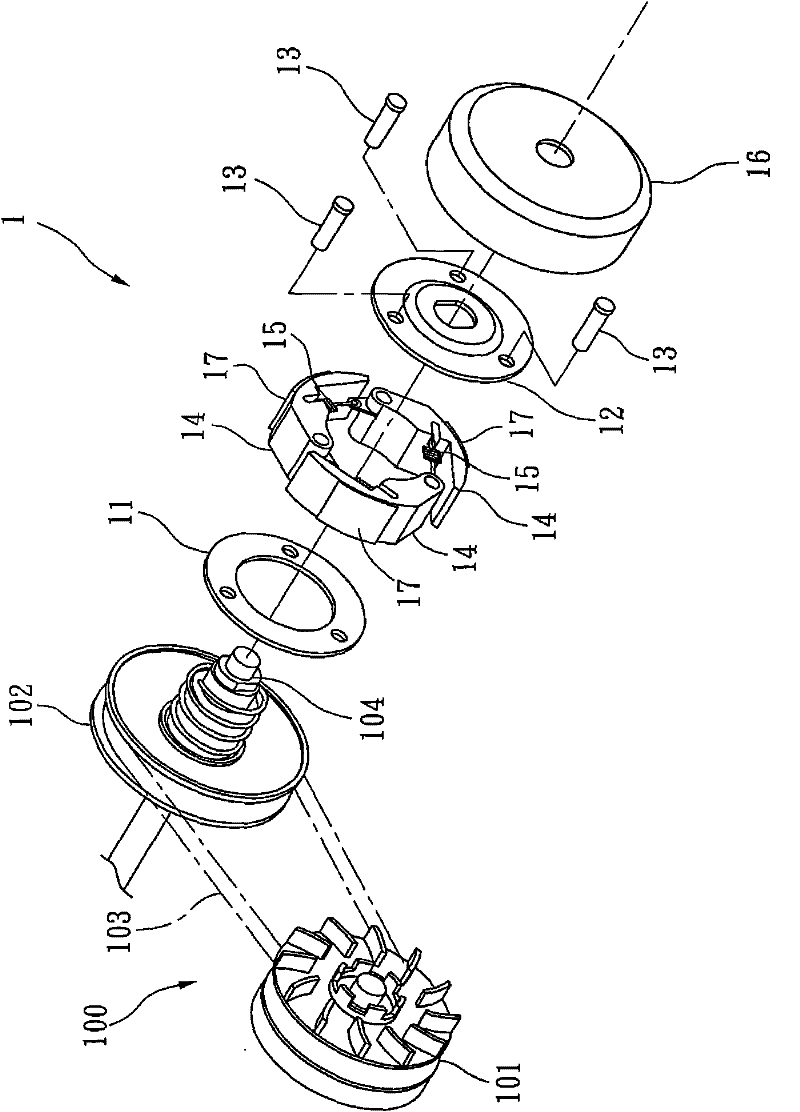
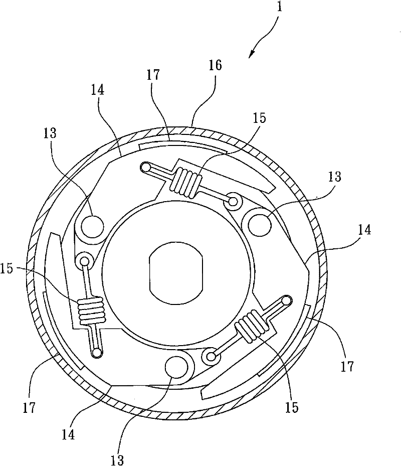
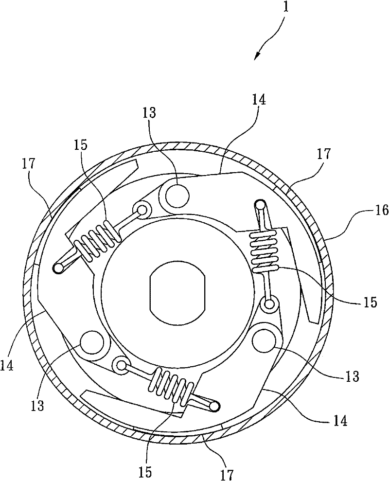
[0074] refer to Figure 4 The first preferred embodiment of the centrifugal clutch 2 of the present invention includes a drive unit 3 , a friction unit 4 located in the drive unit 3 , and an auxiliary unit 5 that assists in driving the friction unit 4 .

[0075] The drive unit 3 includes a base plate 31 and a drive plate 32 arranged at intervals, wherein the base plate 31 is formed with a plurality of positioning holes 311, and the drive plate 32 has a mounting portion 321, a mounting portion 321 The flange portion 322 extending radially outward from the bottom edge, a pluralit...


PUM


Abstract

A centrifugal clutch is disclosed, which comprises a drive unit, a friction unit and an assistant unit. The drive unit comprises a base disc and a drive disc. The friction unit comprises a plurality of shaft rods, a plurality of centrifugal counter weights pivoted on each shaft rod, a plurality of friction pieces disposed on each centrifugal counter weight, a plurality of elastic elements connecting the two adjacent centrifugal counter weights, and an outer cover surrounding the friction pieces. The assistant unit comprises a plurality of location pins, a plurality of drive pins, a plurality of linkage pieces sleeved on the location pins and the drive pins, and a location ring disposed on the drive disc. An acting force on each centrifugal counter weight is increased, and the friction force between each centrifugal counter weight and the outer cover is increased by the drive pins, the linkage pieces and the location pins, thereby efficiently avoiding a slip as well as reducing friction heat and vibration.

Description

【Technical field】 [0001] The present invention relates to a clutch, in particular to a centrifugal clutch. 【Background technique】 [0002] refer to figure 1 , the existing centrifugal clutch 1 is arranged on a transmission system 100 . The transmission system 100 includes a driving wheel 101, a driven wheel 102 spaced apart from the driving wheel 101, a set piece 103 covering the driving wheel 101 and the driven wheel 102, and a penetrating wheel 102 extending through the driven wheel 102. drive shaft 104 . [0003] refer to figure 2 , 3 , and together with review figure 1 The centrifugal clutch 1 includes a base plate 11 disposed on the driven wheel 102, a drive plate 12 spaced apart from the base plate 11, and a plurality of pivot shafts passing through the base plate 11 and the drive plate 12. 13. A plurality of centrifugal counterweights 14 pivotally arranged on each pivot 13 and between the base plate 11 and the drive plate 12, a plurality of springs 15 connectin...

Claims


Application Information

Patent Timeline
IPC IPC(8): F16D43/18
CPCF16D43/18F16D2043/145
Inventor 朱启豪谭镇麒巫善睿
Owner KYMCO
Why Eureka
Try Eureka