Marine big shaft-diameter and excellent following-performance mechanical seal device

A mechanical sealing device and follow-up technology, which is applied in the direction of engine sealing, mechanical equipment, engine components, etc., can solve the problem that the moving ring and the static ring cannot be attached together at all times, the leakage of the mechanical sealing device, and the lack of elastic components quick question

Inactive Publication Date: 2012-05-09
朱方文
View PDF0 Cites 3 Cited by
  • Summary
  • Abstract
  • Description
  • Claims
  • Application Information

AI Technical Summary

Problems solved by technology

[0004] Due to factors such as hull vibration, radial runout and eccentricity of the rotating shaft, and installation quality of the sealing device during the operation of the actual ship, the moving ring and the static ring cannot be fitted together all the time, especially when the rotating shaft is eccentric. Since it is fixed with the rotating shaft, its axis will deviate with the deviation of the rotating shaft, while the static ring remains relatively stationary with the hull, so its axis does not deviate, so the contact end surface of the moving ring and the static ring will be offset due to the axis And there is a gap, which leads to the leakage of the mechanical seal device. Although there are elastic elements to compensate, because the dynamic and static rings do not have the deflection function and the mass and inertia of the dynamic and static rings are large, the elasticity of the elastic elements is often too late. Rapid and timely compensation. In hundreds of thousands of tons and ultra-large ocean engineering ships, the diameter of the drive shaft sometimes reaches about 1 meter. The diameter of the moving ring or the static ring is larger, and the mass and inertia are also larger. It is prominent, and there is no better solution yet

Method used


Image

  • Marine big shaft-diameter and excellent following-performance mechanical seal device
  • Marine big shaft-diameter and excellent following-performance mechanical seal device
  • Marine big shaft-diameter and excellent following-performance mechanical seal device

Examples


Embodiment Construction

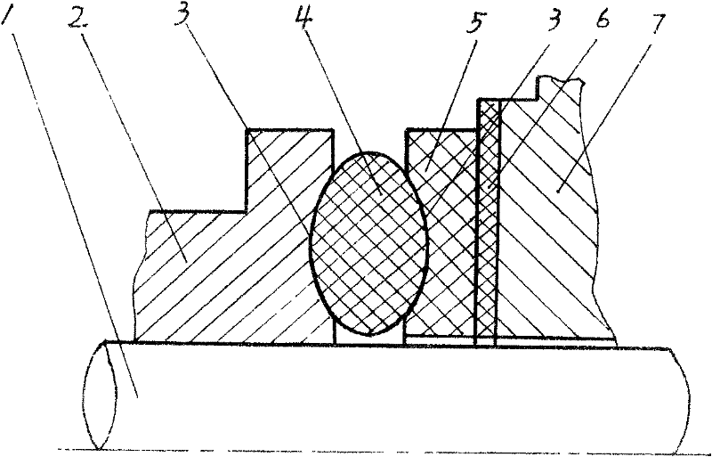
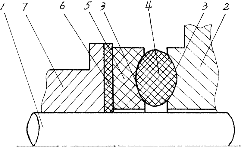
[0023] figure 1 Among them, the sealing ring seat 2 is fixedly connected to the rotating shaft 1 and rotates together with the rotating shaft 1, and an elastic sealing ring 4 is installed between the sealing ring 5 and the sealing ring seat 2, and the elastic sealing ring 4 is a rubber "O" type The elastic sealing ring 4 in the figure is in the state of being deformed under pressure to provide elastic force, and the end face sealing pair is in the sealing state. Both the elastic sealing ring 4 and the sealing ring 5 and between the elastic sealing ring 4 and the sealing ring seat 2 are connected by a concave-convex tongue-and-groove structure 3, and the tongue-and-groove structure 3 is a tongue-and-groove structure composed of an arc-shaped groove and an arc-shaped tenon. . Thereby the radial positioning of the elastic sealing ring 4 and the sealing ring 5 is realized, and the other sealing ring seat 7 and the supported and driven sealing ring 6 are fixedly connected with the...


PUM


Abstract

The invention relates to marine equipment, particularly to the improvement on marine mechanical seal devices, and discloses a marine big shaft-diameter and excellent following-performance mechanical seal device, which includes two sealing rings and sealing ring bases, wherein the two sealing rings are oppositely arranged and form an end surface seal pair, the two sealing ring bases are used for supporting and driving the two sealing rings respectively; in the two sealing ring bases, one elastic seal ring is installed between the at least one sealing ring base and the sealing ring driven and supported by the sealing ring base, the elastic seal ring and the sealing ring are connected through a concavo-convex tongued and grooved structure and radially located; the elastic seal ring and the sealing ring base are connected through a concavo-convex tongued and grooved structure and radially located; and the sealing rings made of high-molecular self-lubricating materials enable the end surface seal pair to have excellent following performance, so as to quickly and timely compensate and improve the sealing effect.

Description

technical field [0001] The invention relates to ship equipment, in particular to the improvement of ship mechanical sealing devices. Background technique: [0002] Marine sealing devices are widely used in the sealing of ship stern shafts or drive shafts of outboard electric propellers. It is used to prevent seawater from intruding into the ship from the stern shaft, or to prevent seawater from entering the interior of the equipment from the propulsion shaft of the underwater electric propeller outside the ship. The quality of its sealing performance is directly related to the safe operation of the ship, and it is one of the important equipment of the ship. . [0003] The current mechanical seal device includes two seal rings that are oppositely arranged and constitute an end face seal pair, and a seal ring seat that supports and drives the two seal rings. A seal ring seat and the supported and driven seal ring surround the rotating shaft (or The shaft bushing, which is in...

Claims


Application Information

Patent Timeline
Patent Type & Authority Applications(China)
IPC IPC(8): F16J15/18
Inventor 朱方文
Owner 朱方文
Why Eureka
Try Eureka