X-ray tube with improved vacuum processing

一种X射线管、X射线的技术,应用在X射线管的处理领域

Inactive Publication Date: 2012-05-09
GENERAL ELECTRIC CO
View PDF5 Cites 7 Cited by
  • Summary
  • Abstract
  • Description
  • Claims
  • Application Information

AI Technical Summary

Problems solved by technology

These particles can lead to eventual failure of the tube over time

Method used


Image

  • X-ray tube with improved vacuum processing
  • X-ray tube with improved vacuum processing
  • X-ray tube with improved vacuum processing

Examples


Embodiment Construction

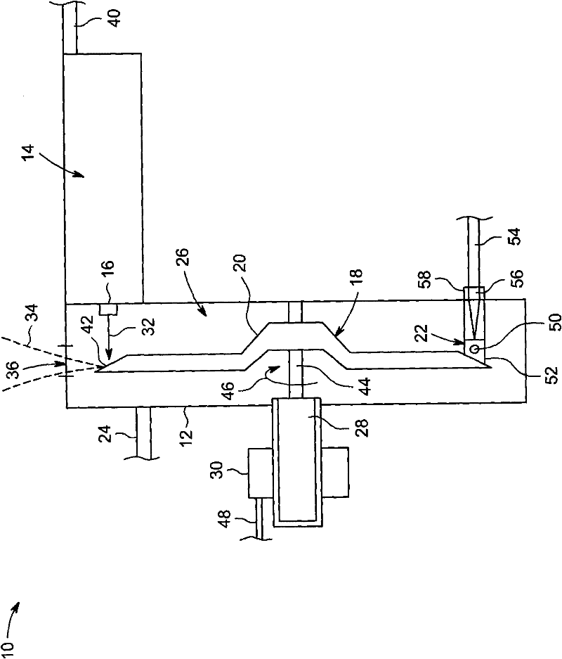
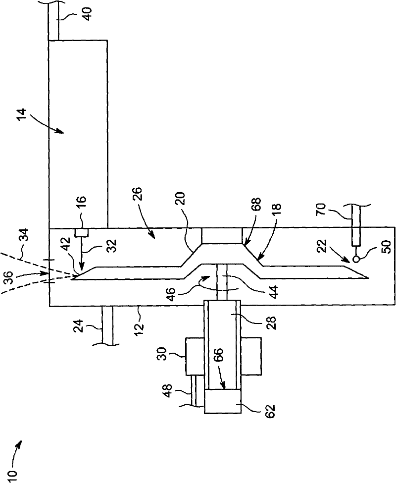
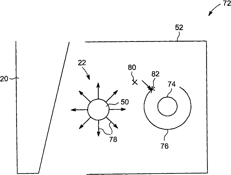
[0014] This approach is directed to the integration of the sub-cathode within the X-ray tube. This sub-cathode can be employed in processing X-ray tubes. More specifically, during X-ray tube processing, the sub-cathode employed in this approach may be heated by an electrical current, which causes electrons to be emitted from the sub-cathode towards the anode and outgasses the X-ray tube. The use of a secondary cathode for degassing does not use the X-ray tube primary cathode during processing and can extend the life of the primary cathode. Additionally, the sub-cathode can be used to detect vacuum integrity within the X-ray tube during processing and post-processing and serve as a diagnostic tool for potential X-ray tube errors and failures related to high voltages.

[0015] In this manner, the secondary cathode can eliminate the need for standard bakeout techniques for processing X-ray tubes and / or reduce the processing time to evacuate these tubes during manufacture. In on...


PUM


Abstract

In one embodiment, an X-ray tube (10) includes an electron beam source (14) including a primary cathode (16) configured to emit an electron beam (32) and an anode assembly (18) including an anode (20) configured to receive the electron beam (32) and to emit X-rays (34) when impacted by the electron beam (32). The X-ray tube (10) also includes an enclosure (12), at least the primary cathode (16) and the anode (20) being disposed in the enclosure (12), and a secondary cathode (22) disposed in the enclosure (12) and configured to emit electrons to impact the anode (20) for degassing the enclosure (12).

Description

technical field [0001] The subject matter disclosed herein relates to X-ray tube radiation sources, and more particularly to the handling of X-ray tubes. Background technique [0002] In non-invasive imaging systems, x-ray tubes are used as sources of x-ray radiation in projection x-ray systems, fluoroscopy systems, tomosynthesis systems, and computed tomography (CT) systems. Typically, an X-ray tube includes a cathode and an anode. Emitters within the cathode emit a stream of electrons through the thermionic effect in response to heat caused by the applied current. The anode includes a target struck by the electron stream. Thus, the target generates X-ray radiation and heat. Such systems are useful in medical settings, but also for parcel and package screening, component inspection, various research settings, and the like. [0003] Radiation is passed through a subject of interest, such as a patient, and a portion of the radiation strikes a detector or photographic film...

Claims


Application Information

Patent Timeline
Patent Type & Authority Applications(China)
IPC IPC(8): H01J35/24H01J35/06H01J35/08H01J35/16
CPCH01J35/06H01J2235/20H01J35/20H01J35/064H01J35/066
Inventor L·唐E·B·比尔R·M·罗菲尔斯K·科皮塞蒂
Owner GENERAL ELECTRIC CO
Why Eureka
Try Eureka