3D point locator system

a point locator and point technology, applied in the direction of electric programme control, program control, instruments, etc., can solve the problem of illusory apparent cooperation between the spots, and achieve the effect of reducing the distance between the spots

Inactive Publication Date: 2005-05-12
BIERRE PIERRE
View PDF0 Cites 73 Cited by
  • Summary
  • Abstract
  • Description
  • Claims
  • Application Information

AI Technical Summary

Benefits of technology

[0033] Beam Intersection. An arbitrary 3D point P=[x y z] may be pinpointed visually by making two pencil light beams intersect at P. While a reflective haze of smoke would be required to see the “X” formed where the beams intersect, as a practical matter, placement of any solid object in the path of both beams near their intersection will cause two spots of light to appear. As the reflecting object is manipulated in the direction of ...

Problems solved by technology

When two beam throwers are set up and operating to crisscross beams...

Method used


Image

  • 3D point locator system
  • 3D point locator system
  • 3D point locator system

Examples


Embodiment Construction

3D Direction Vectors and Rotators

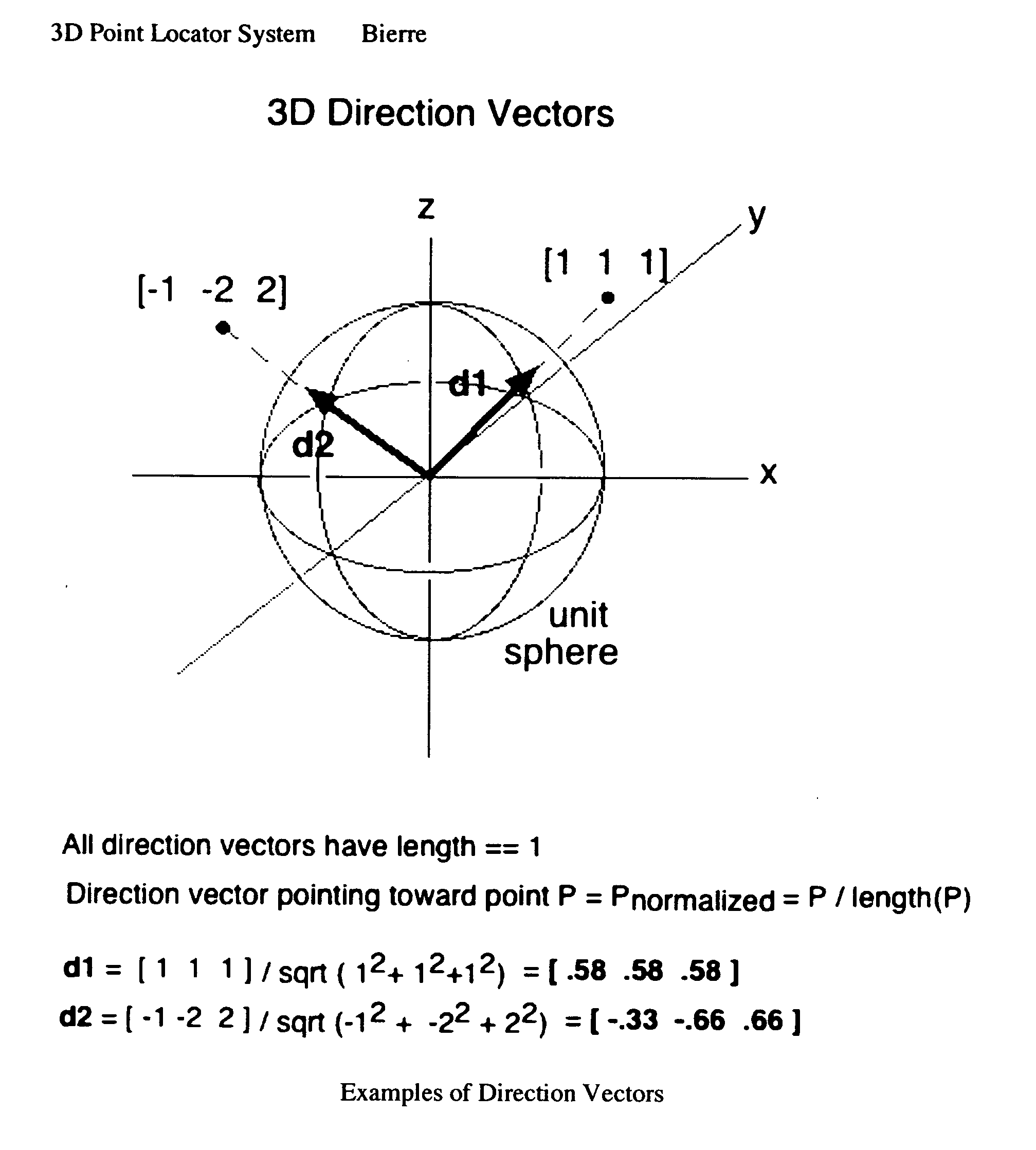
[0079] The geometric algorithms underlying the invention are based on direction vector processing. Directions in 3D space are represented as vectors of unit length, with tails at the origin, and heads on the unit sphere. FIG. 4 illustrates two distinct directions, d1 and d2, specified computationally as direction vectors.

[0080] Rotation of a 3D coordinate space about the origin can be managed in a similarly direct manner. Given that the rotation transforms points from old coordinates into new coordinates, one need only furnish the new x, y, z axes in old coordinates to specify the rotation. Each new axis is expressed as a direction vector. As a group, the new axes must maintain the same spatial relationship among each other as the basis vectors in the old space (by convention, only right-handed axes are used).

[0081] Rotating a point P into its new coordinates P′ is carried out using the matrix operation:

P′=P·(newXaxis newYaxis newZaxis)=P·R

whe...


PUM


Abstract

An automated system and method of geometric 3D point location. The invention teaches a system design for translating a CAD model into real spatial locations at a construction site, interior environment, or other workspace. Specified points are materialized by intersecting two visible pencil light beams there, each beam under the control of its own robotic ray-steering beam source. Practicability requires each beam source to know its precise location and rotational orientation in the CAD-based coordinate system. As an enabling sub-invention, therefore, an automated system and method for self-location and self-orientation of a polar-angle-sensing device is specified, based on its observation of three (3) known reference points. Two such devices, under the control of a handheld unit downloaded with the CAD model or pointlist, are sufficient to orchestrate the arbitrary point location of the invention, by the following method: Three CAD-specified reference points are optically defined by emplacing a spot retroreflector at each. The user then situates the two beam source devices at unspecified locations and orientations. The user then trains each beam source on each reference point, enabling the beam source to compute its location and orientation, using the algorithm of the sub-invention. The user then may select a CAD-specified design point using the handheld controller, and in response, the handheld instructs the two beam sources to radiate toward the currently selected point P. Each beam source independently transforms P into a direction vector from self, applies a 3×3 matrix rotator that corrects for its arbitrary rotational orientation, and instructs its robotics to assume the resultant beam direction. In consummation of the inventive thread, the pair of light beams form an intersection at the specified point P, giving the worker visual cues to precisely position materials there. This design posits significant ease-of-use advantages over construction point location using a single-beam total station. The invention locates the point effortlessly and with dispatch compared to the total station method of iterative manual search maneuvering a prism into place. Speed enables building features on top of point location, such as metered plumb and edge traversal, and graphical point selection. The invention eliminates the need for a receiving device to occupy space at the specified point, leaving it free to be occupied by building materials. The invention's beam intersection creates a pattern of instantaneous visual feedback signifying correct emplacement of such building materials. Unlike surveying instruments, the invention's freedom to situate its two ray-steering devices at arbitrary locations and orientations, and its reliance instead on the staking of 3 reference points, eliminates the need for specialized surveying skill to set up and operate the system, widening access to builders, engineers, and craftspeople.

Description

CROSS-REFERENCE TO RELATED APPLICATIONS [0001] This application is filed pursuant to U.S. Provisional Patent Application 60 / 519,411 filed Nov. 12, 2003.STATEMENT REGARDING FEDERALLY SPONSORED RESEARCH OR DEVELOPMENT [0002] None of the inventive work being applied for herein was sponsored by the U.S. Government. RELATED ART [0003] U.S. Class / Subclass searched [0004] 33 / 1G Geometrical Instruments / Layout [0005] U.S. Pat. No. 6,505,406 [0006] 20020014015 [0007] U.S. Pat. No. 6,415,518 [0008] 33 / 1CC Geometrical Instruments / Remote Point Locating [0009] U.S. Pat. No. 6,437,708 [0010] 33 / 1T Geometrical Instruments / Theodolite, Optical Readout [0011] U.S. Pat. No. 5,091,869 [0012] U.S. Pat. No. 5,007,175 [0013] U.S. Pat. No. 4,988,192 [0014] 356 / 3.1 Optics / Triangular Ranging to a Point w / 2 or More Projected Beams [0015] (this subclass is about location sensing technologies—Claim 2 should be cross-referenced to this class) [0016] 701 / 216 Data Processing—Vehicles, Navigation, and Relative Locat...

Claims


Application Information

Patent Timeline
IPC IPC(8): G01C15/00G05B19/04G05B19/418G06F19/00
CPCG01C15/002
Inventor BIERRE, PIERRE
Owner BIERRE PIERRE
Why Eureka
Try Eureka