Optical disc recording apparatus, controlling method of the same, and optical disc

Inactive Publication Date: 2007-08-30
KK TOSHIBA
View PDF4 Cites 67 Cited by
  • Summary
  • Abstract
  • Description
  • Claims
  • Application Information

AI Technical Summary

Benefits of technology

[0012] It is an object of the invention to provide an optical disk recording a

Problems solved by technology

In the recording/reproducing apparatus for a holographic optical disc, when the intensity distribution of the light beam generated by a laser for recording/reproducing in the diametric direction does not obey Gaussian distribution, when there is an individual difference in the recording/reproducing semiconductor laser, or when there is an assembly variation of the optical sy

Method used


Image

  • Optical disc recording apparatus, controlling method of the same, and optical disc
  • Optical disc recording apparatus, controlling method of the same, and optical disc
  • Optical disc recording apparatus, controlling method of the same, and optical disc

Examples


first embodiment

[0031] In the first embodiment, a red laser beam having a wavelength of about 650 nm or an infrared laser beam having a wavelength of about 780 nm can be used as the servo laser beam 108 having the first wavelength. Also, an available semiconductor laser beam or a blue-violet laser beam having a wavelength of 405 nm in terms of flexibility in the design of the hologram recording medium layer can be used as the recording / reproducing laser beam 109 having the second wavelength. Alternatively, a green laser beam having a wavelength of 532 nm may be used as the recording / reproducing laser beam 109.§

[0032] The transparent gap layers 103 and 105 transmit the servo laser beam 108 and the recording / reproducing laser beam 109. The gap layer 103 is formed by coating a material, such as UV resin, on the substrate 101 using, for example, a spin coating method. The gap layer 105 is formed by coating a material, such as UV resin, on the dichroic mirror layer 104 using, for example, a spin coating...

second embodiment

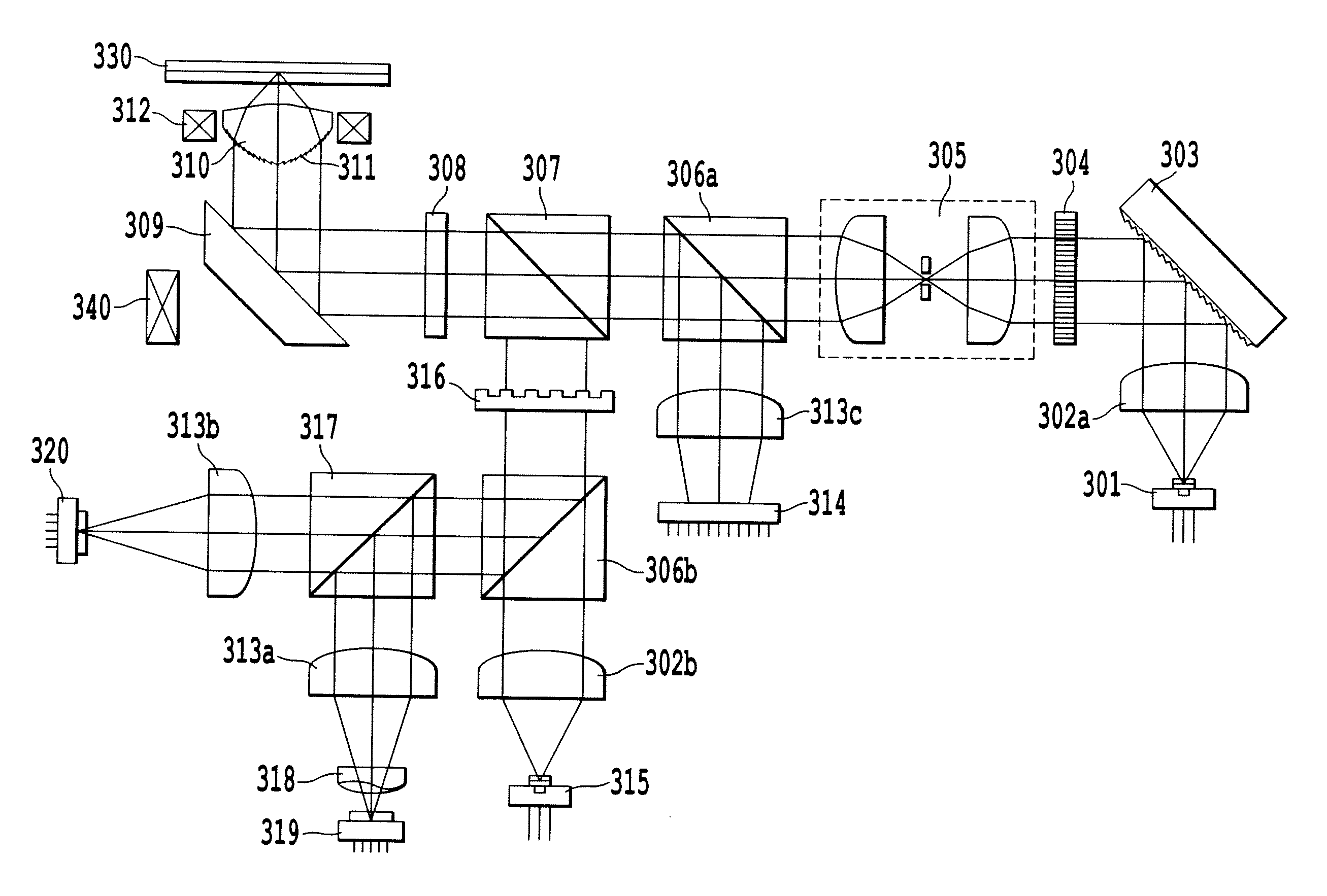
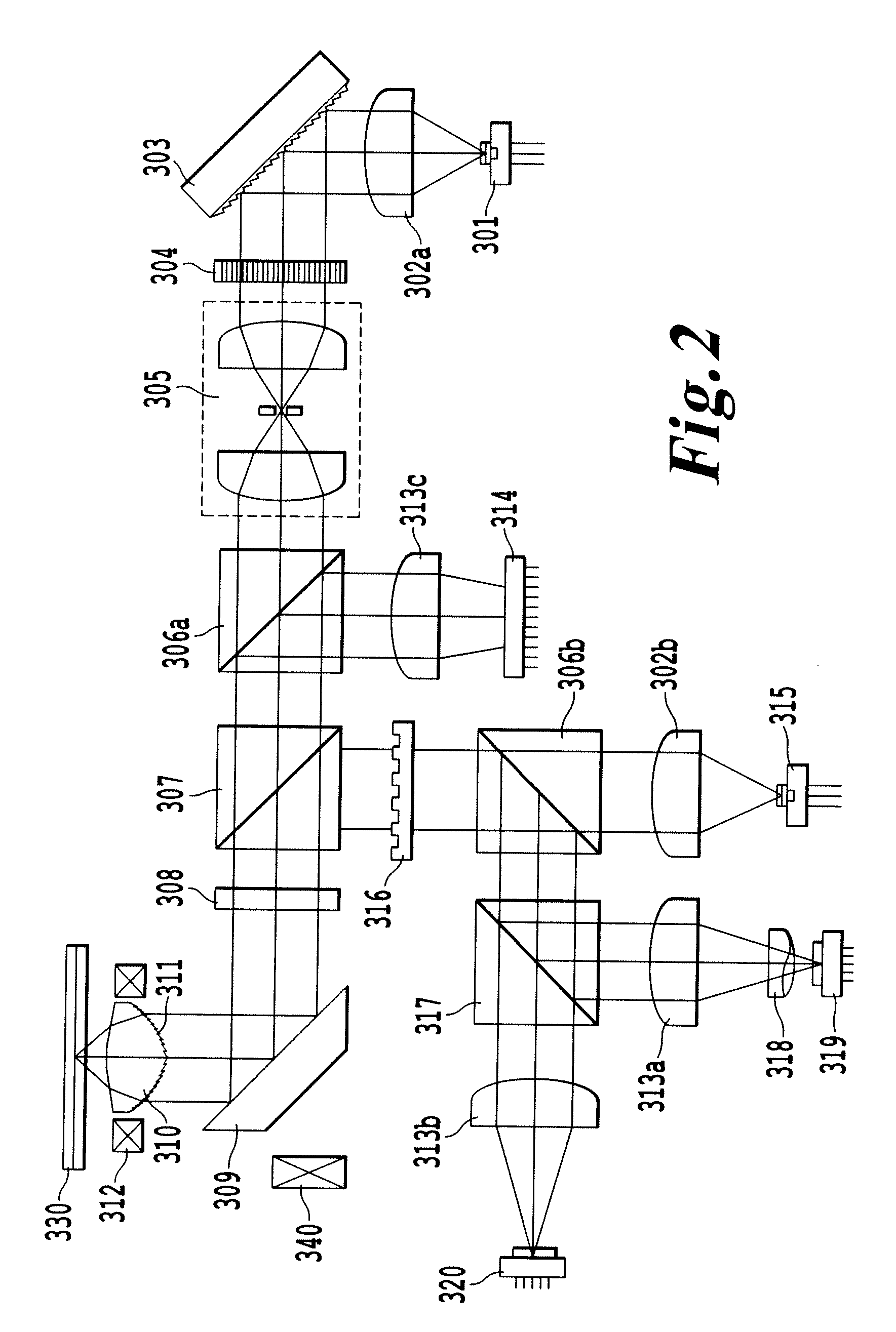
[0042] The information beam 401 carries information on a binary pattern obtained by digitally encoding information to be recorded and incorporating an error correction code into the encoded digital code. The amount of data in an information beam region depends on the spatial light modulator, the number of pixels of a light-sensitive image sensing device, or an encoding method and is about 10 to 20 Kbits per frame. In this embodiment, the binary pattern composed of “0” and “1” is assumed as the information to be recorded. However, a multi-valued pattern can be used as the information to be recorded. In this case, it is possible to remarkably increase the amount of data per frame. The multi-valued pattern will be described in detail in a

[0043] The spatial filter 305 includes two lenses and a pinhole. The reference beam 402 and the information beam 401 emitted from the spatial light modulator 304 are incident on the spatial filter 305. The spatial filter 305 removes unnecessary high-or...


PUM


Abstract

An optical disk recording apparatus and method utilize a recording beam source, a spatial light modulator that modulates a recording radiation beam into an information beam carrying information and a reference beam, a focusing unit that focuses the information beam and the reference beam onto an information recording layer, an image sensing device that detects intensity distribution of the information beam, and a control unit. The control unit controls the spatial light modulator on the basis of the intensity distribution detected by the image sensing device. An optical disk recording apparatus, and a control method thereof, thereby has a high signal-to-noise ratio.

Description

CROSS-REFERENCE TO RELATED APPLICATIONS [0001] This application is based upon and claims the benefit of priority from the prior Japanese Patent Application No. 2006-053599, filed Feb. 28, 2006, the entire contents of which are incorporated herein by reference. BACKGROUND OF THE INVENTION [0002] 1. Field of the Invention [0003] The present invention relates to an optical disk recording apparatus for recording information as a hologram on an optical disk, a method of controlling the optical disk recording apparatus, and an optical disk. [0004] 2. Description of the Background Art [0005] Recently, a high-density optical disc of a volume recording type using a hologram (hereinafter, referred to as “a holographic optical disc”) and a recording / reproducing apparatus for a holographic optical disc have been developed to be put into practical use. A holographic optical disc recording method is a method of recording information by making an information beam carrying an image and a reference ...

Claims


Application Information

Patent Timeline
IPC IPC(8): G11B7/00
CPCG11B7/0065G11B7/083G11B7/0938G11B7/24044G11B7/128G11B7/1398G11B7/126
Inventor YAOITA, AKIKOTATSUTA, SHINICHIHIRAO, AKIKOMATSUMOTO, KAZUKI
Owner KK TOSHIBA
Why Eureka
Try Eureka