
Vacuum film forming apparatus and method for detecting position of shutter plate of vacuum film forming apparatus

A film forming device and vacuum technology, applied in vacuum evaporation plating, ion implantation plating, coating, etc., can solve the problems of film formation, exposure, and extension of the workbench

Active Publication Date: 2014-01-15
ULVAC INC
View PDF3 Cites 0 Cited by
  • Summary
  • Abstract
  • Description
  • Claims
  • Application Information

AI Technical Summary

Problems solved by technology

[0005] However, if the shutter is held by the arm in a state where it is shifted from a preset holding reference position, when placed on the table, a part of the table may protrude from the shutter and be exposed.
If a part of the stage protrudes from the shutter, the exposed part of the stage may be formed into a film when dummy sputtering is performed, and the formed film may scatter, which becomes a problem when forming a film on a target substrate. Problems such as impurities

Method used


Image

  • Vacuum film forming apparatus and method for detecting position of shutter plate of vacuum film forming apparatus
  • Vacuum film forming apparatus and method for detecting position of shutter plate of vacuum film forming apparatus
  • Vacuum film forming apparatus and method for detecting position of shutter plate of vacuum film forming apparatus

Examples


Embodiment Construction

[0031] Next, a vacuum film forming apparatus according to the present invention will be described based on the drawings. In addition, this embodiment is an example given and demonstrated for better understanding of the gist of invention, Unless otherwise specified, this invention is not limited. In addition, in the drawings used in the following description, in order to facilitate understanding of the features of the present invention, main parts may be shown enlarged for convenience, and the dimensional ratio of each component is not necessarily the same as the actual one.

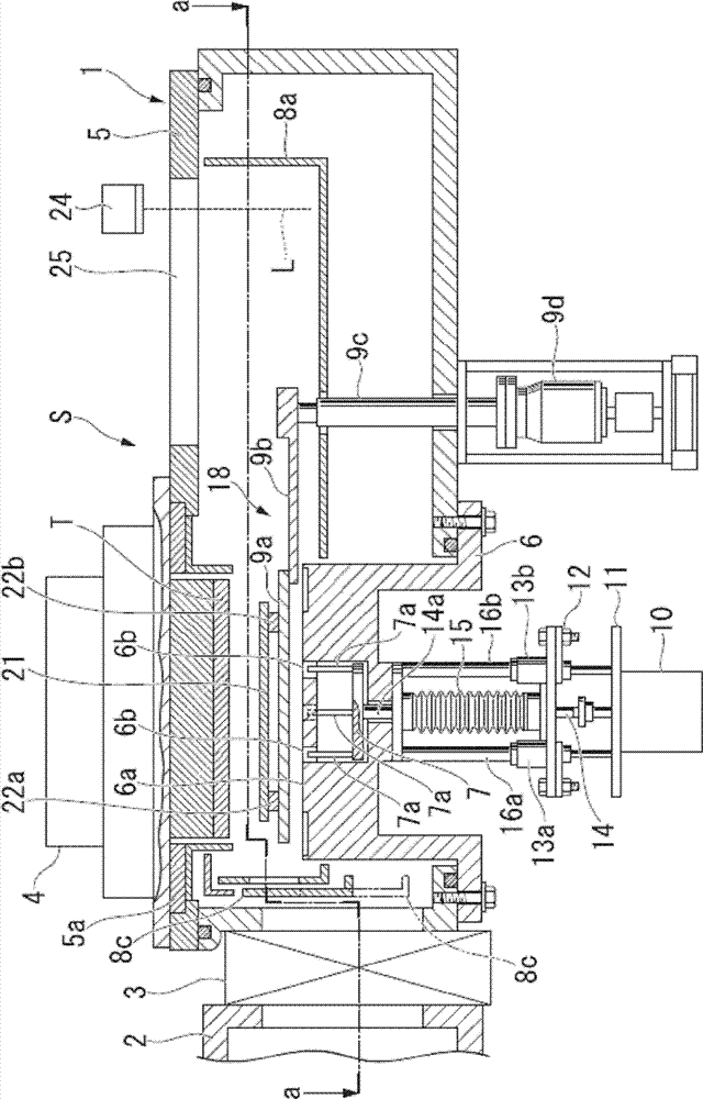
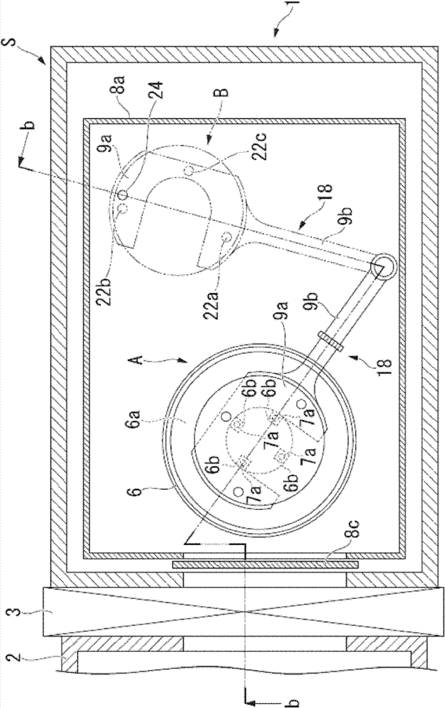
[0032] figure 1 It shows a structural example of the vacuum film forming apparatus related to the present invention ( figure 2 b-b direction) side sectional view, figure 2 yes figure 1 The a-a in the top view section view.

[0033] The vacuum film forming apparatus S includes a chamber 1 defining a film forming chamber, and is connected to a transfer chamber 2 adjacent to the left via a gate valve 3...


PUM


Abstract

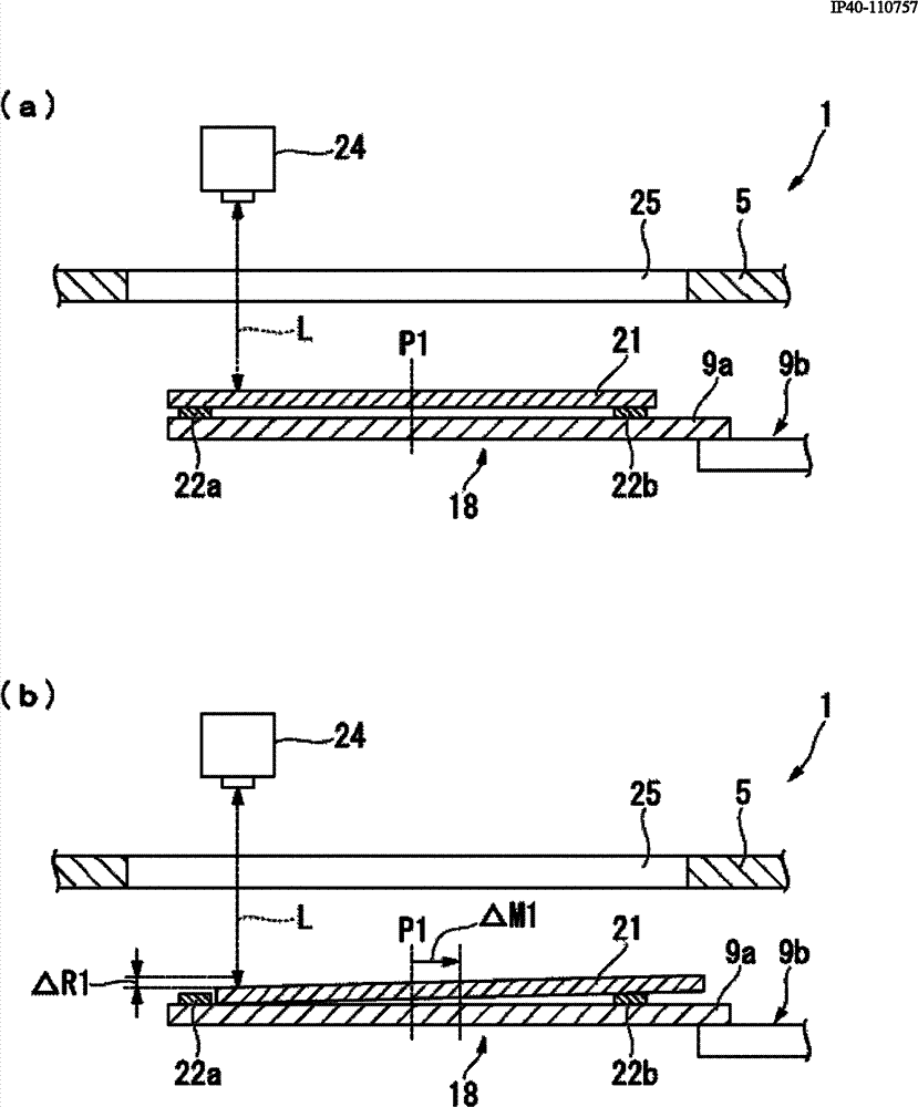
At the time of detecting a position of a shutter plate, a laser light, for instance, is radiated from a detector (an optical sensor). The radiated laser light reaches the shutter plate through a window of a chamber. Then, the laser light is reflected by the surface of the shutter plate and re-enters the detector. The detector detects the time required from the emission of the laser light to the entry of the reflected light.

Description

technical field [0001] The present invention relates to a vacuum film forming apparatus and a method for detecting a position of a shutter of the vacuum film forming apparatus. Specifically, it relates to a technique for detecting displacement of a holding position of a shutter with high accuracy. Background technique [0002] For example, in a vacuum film-forming device that forms a thin film on the film-forming surface of a substrate, in order to clean the surface of the target as a film-forming material and stabilize the film-forming characteristics, film-forming (sputtering) is performed on the substrate of the film-forming target. ) before the formal process, film formation (false sputtering) is generally performed on a dummy substrate (hereinafter also referred to as a barrier) (for example, refer to Patent Document 1). [0003] When performing such pseudo-sputtering, sputtering is performed with a baffle placed on a table on which an object to be filmed is placed. Wh...

Claims


Application Information

Patent Timeline
Patent Type & Authority Patents(China)
IPC IPC(8): C23C14/34C23C14/54
CPCH01J37/3447H01J37/34C23C14/34C23C14/54
Inventor 藤井佳词
Owner ULVAC INC
Learn More