
Grinding device

A grinding and mounting technology, which is applied in the direction of grinding drive device, grinding workpiece support, grinding machine tool parts, etc., can solve the problems of camera cost, wafer crack, and insufficient center position alignment accuracy

Active Publication Date: 2012-04-11
DISCO CORP
View PDF2 Cites 0 Cited by
  • Summary
  • Abstract
  • Description
  • Claims
  • Application Information

AI Technical Summary

Problems solved by technology

[0010] The contact-type centering device disclosed in Patent Document 1 has the problem of cracks on the wafer or insufficient alignment accuracy of the calculated center position.
In addition, since the semiconductor wafer alignment device disclosed in Patent Document 2 uses a plurality of cameras, there are problems in that the cost of the cameras is high and the adjustment of the positions of the cameras is labor-intensive.

Method used


Image

  • Grinding device
  • Grinding device
  • Grinding device

Examples


Embodiment Construction

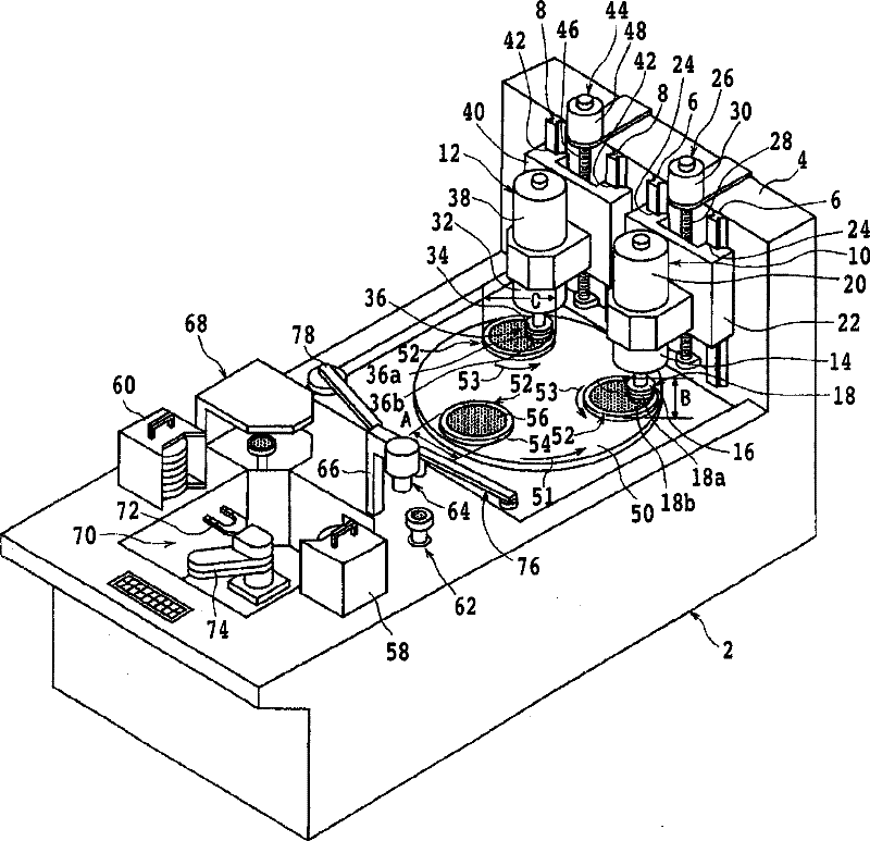
[0041] A grinding device according to an embodiment of the present invention will be described in detail below with reference to the drawings. refer to figure 1 , figure 1 A perspective view showing a grinding device according to an embodiment of the present invention. The grinding device includes a substantially cuboid-shaped device housing 2 . The vertical support plate 4 is adjacent to the upper right end of the device housing 2 .

[0042] Two pairs of guide rails 6 and 8 extending in the vertical direction are provided on the inner side of the vertical support plate 4 . A rough grinding unit 10 is vertically movable to one guide rail 6 , and a finish grinding unit 12 is vertically movable to the other guide rail 8 .

[0043]The rough grinding unit 10 is constituted to have: a unit housing 14; a grinding wheel 18 mounted on a wheel base 16 which is freely rotatable and mounted on the lower end of the unit housing 14; an electric motor 20 mounted on the The lower end of...


PUM


Abstract

The invention provides a grinding device which comprises a center alignment. The center alignment component comprises a camera shooting component and an offset detecting component which detects the offset of the center of the wafer and the center of the maintain arm according to the information of picture shot by the camera shooting component. The offset detecting component detects the coordinates of more than three points on the external periphery of the wafer according to the information of the picture being shot so as to obtain the center of the wafer, and also detects the offset of the center of the wafer and the center of the maintain arm. The maintain arm is correspondingly corrected relative to the offset so as to load and place the wafer in the way of locating the center of the wafer to the center of the worktable being temporarily placed, a wafer moving component is set into one that can rotate in such a way: an absorption part carves a round arc track which passes through the center of the worktable being temporarily placed and the center of the chuck worktable, and the wafer moving component locates the center of the wafer to the center of the chuck worktable and relieves the absorption.

Description

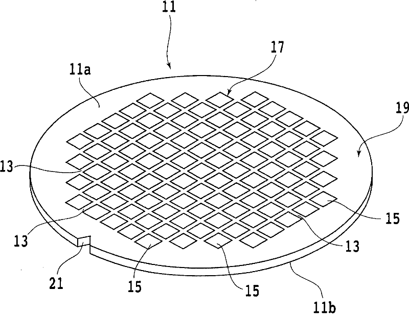
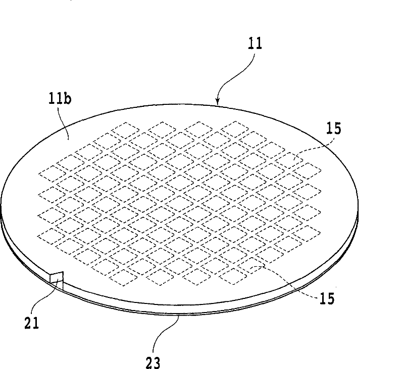
technical field [0001] The present invention relates to a grinding apparatus for grinding the backside of a wafer on which a plurality of devices are formed. Background technique [0002] In the semiconductor device manufacturing process, on the surface of a semiconductor wafer having a substantially disk shape, a plurality of regions are divided by dividing lines called streets arranged in a grid pattern, and ICs are formed on the divided regions. Integrated Circuit: integrated circuit), LSI (large scale integration: large scale integrated circuit) and other devices. Then, the semiconductor wafer is divided into individual semiconductor chips by cutting the semiconductor wafer along the lanes with a cutting device. [0003] The divided wafer is formed to a predetermined thickness by grinding or etching the back surface before being cut along the lanes. In recent years, in order to achieve weight reduction and miniaturization of electrical equipment, the thickness of the w...

Claims


Application Information

Patent Timeline
Patent Type & Authority Patents(China)
IPC IPC(8): H01L21/304B24B7/22B24B41/06B24B49/12H01L21/68
CPCB24B7/228B24B47/22
Inventor 桑名一孝福士畅之力石利康久保徹雄
Owner DISCO CORP
Learn More