Arrangement and method to retrofit a wind turbine

A technology for wind turbines and hubs, which is applied to wind turbines, wind turbine components, and wind turbines in the same direction as the wind, can solve problems such as time-consuming and expensive

Inactive Publication Date: 2012-05-16
SIEMENS AG
View PDF5 Cites 2 Cited by
  • Summary
  • Abstract
  • Description
  • Claims
  • Application Information

AI Technical Summary

Problems solved by technology

[0005] This modification work is time consuming and expensive

Method used


Image

  • Arrangement and method to retrofit a wind turbine
  • Arrangement and method to retrofit a wind turbine
  • Arrangement and method to retrofit a wind turbine

Examples


Embodiment Construction

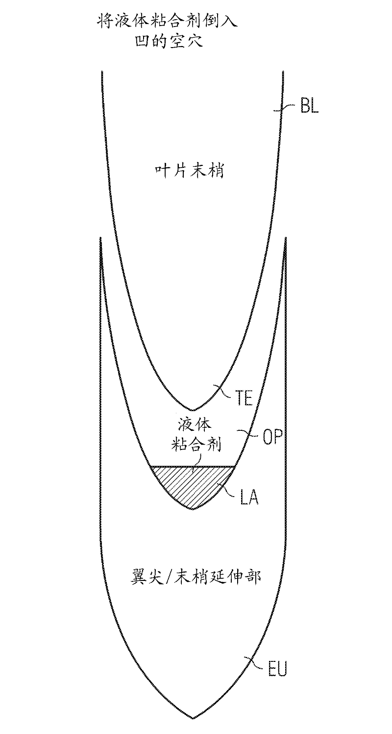
[0032] figure 1 A first step in retrofitting a wind turbine blade according to the invention is shown.

[0033] A blade BL of a wind turbine shows a tip end TE prepared for connection with an extension unit EU.

[0034] The extension unit EU is designed as a wingtip and is prepared to increase the surface area of ​​the blade BL.

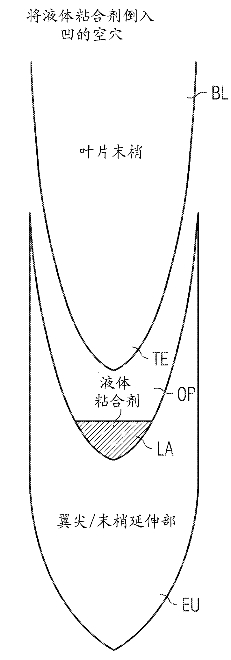
[0035] Beside this extension unit EU, an opening OP is arranged. The opening OP may be shaped as a cavity prepared to receive the tip part of the blade BL - the tip end TE.

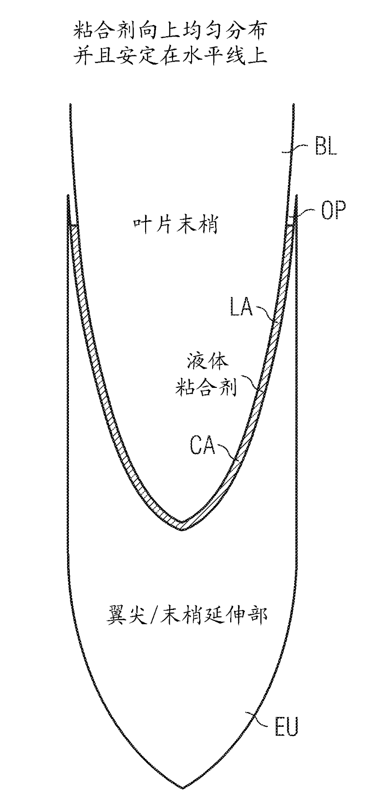
[0036] The opening OP is filled with a liquid adhesive LA.

[0037] The extension unit EU is connected to the blade BL by an adhesive LA applied at least partially in the opening OP.

[0038] The opening OP is shaped and designed as a concave cavity and / or indentation of the tip end TE of the blade BL. Consequently, the extension unit EU is finally connected to the blade BL in a form-fitting manner.

[0039] figure 2 A second step of retrofitting a wind turbine blade acc...


PUM


Abstract

The invention relates to an arrangement and to a method to retrofit a wind turbine. According to the invention a wind turbine is retrofitted by at least one of its blades. The blade is prepared for a connection with the hub of the wind turbine. An extension unit is designed and prepared to increase the surface-area of the blade. The extension unit and the blade are designed and arranged to interact with each other by an opening. Thus the opening might be arranged asides the blade and / or asides the extension unit. The extension unit is connected with the blade by an adhesive, which is applied at east partly within the opening.

Description

technical field [0001] The present invention relates to an arrangement and a method for retrofitting a wind turbine. Background technique [0002] Sometimes, existing and installed wind turbines need to be retrofitted to adapt their capacity to the environmental conditions. [0003] For example, the blades of the wind turbine may be detached from the hub of the wind turbine and may be lowered to the ground. A new set of blades longer than the old set can be installed on the hub to increase the wind turbine capacity. [0004] The removed blades can be repaired or even inspected for further use. [0005] This modification work is time consuming and expensive. [0006] Also, where wind turbines are being handled offshore, the work needs to be carried out in calm weather conditions. [0007] In addition, specially designed ships with large cranes are required to remove the old blades and install new ones. Contents of the invention [0008] It is therefore an object of the...

Claims


Application Information

Patent Timeline
Patent Type & Authority Applications(China)
IPC IPC(8): F03D11/00F16B11/00
CPCF03D1/0675F05B2230/60F03D1/0608F05B2230/80F03D1/065F05B2230/23Y02E10/721F05B2240/302Y02E10/72Y02P70/50F05B2240/307
Inventor S.奥尔森J.斯特格H.斯蒂斯达尔
Owner SIEMENS AG
Why Eureka
Try Eureka