Multisection bearing universal balance compass mechanism

A compass and balance technology, applied in the field of automatic adjustment of verticality, can solve the problems of large support span, poor anti-vibration performance, and high cost of use, and achieve improved anti-vibration ability and stability, good adjustment freedom, and extended use The effect of longevity

Active Publication Date: 2014-03-12
704TH RES INST OF CHINA SHIPBUILDING IND CORP
View PDF6 Cites 0 Cited by
  • Summary
  • Abstract
  • Description
  • Claims
  • Application Information

AI Technical Summary

Problems solved by technology

[0003] 1. The existing typical compass mechanism is a two-section adjustment structure (ie, the outer ring 91 and the inner ring 93), which has poor adjustment freedom. When the structural inclination is large, the compass mechanism loses verticality adjustment due to its own structural constraints Ability, or "stuck" phenomenon;
[0004] 2. The support of the inner and outer connecting shafts 92 and 94 of the existing typical compass mechanism adopts sliding bearings, and the sliding friction damping is relatively large, which affects the verticality adjustment function of the mechanism. At the same time, the large span of each support makes it difficult to realize the symmetry of its own structure Larger, the difference in symmetry will further have a greater negative impact on the verticality adjustment effect of the mechanism
[0005] 3. After long-term use on the mechanism, or after use in a vibrating environment, its easily deformable structure and its easy-to-wear sliding bearing will reduce its automatic balance performance, causing the verticality of the installed parts to fail to meet the specified requirements. Therefore, it is necessary to Frequent maintenance or component replacement of the mechanism has a short service life and high cost of use;
[0006] 4. The existing compass mechanism has poor anti-vibration performance. Due to the necessary sliding gap between the supporting contact surfaces, the structure is unstable in use

Method used


Image

  • Multisection bearing universal balance compass mechanism
  • Multisection bearing universal balance compass mechanism
  • Multisection bearing universal balance compass mechanism

Examples


Embodiment Construction

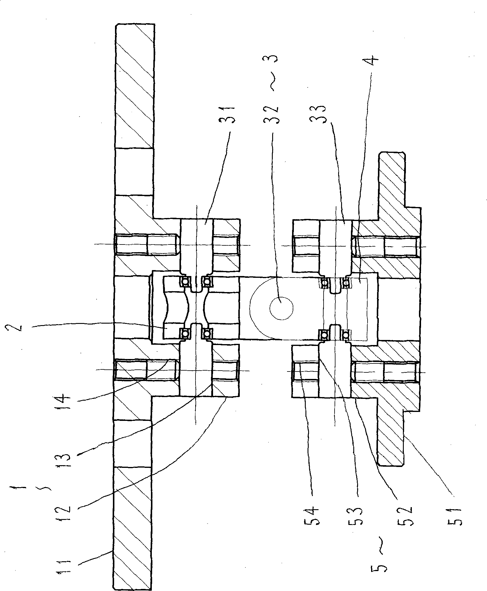
[0020] refer to figure 1 , The multi-section bearing universal balance compass mechanism includes an upper compass frame 1, a fork 2, a hinge assembly 3, a rod-shaped part 4 and a lower compass frame 5, and the figure shows a compass mechanism with a 3-section adjustment structure.

[0021] The upper compass frame 1 has a circular, rectangular or other similarly shaped plate-shaped upper frame body 11, and several through holes can be opened on the upper frame body 11, and the upper compass frame 11 is installed on the hull member or other similar components for piercing bolts. On the component, there are two upper lugs 12 protruding from the bottom surface of the upper frame body 11. The upper frame body 11 and the upper lugs 12 can be cast or welded into one body. The two symmetrical upper lugs 12 have two coaxial upper Shaft holes 13, the left and right shafts 31, 34 of the hinged assembly 3 can be installed on the upper shaft holes 13, the two upper lugs 12 respectively h...


PUM


Abstract

The invention discloses a multisection bearing universal balance compass mechanism, and is mainly used for solving the technical problem of improving the regulating power of the mechanism freedom and the like. The adopted technical scheme of the compass mechanism is as follows: the mechanism is composed of an upper compass frame, a Y-piece, a rod-shaped piece and a lower compass frame, wherein the upper compass frame is articulated with one end of the Y-piece through a first articulated piece of an articulated assembly, the other end of the Y-piece is articulated with one end of the rod-shaped piece through a second articulated piece of the articulated assembly, and the other end of the rod-shaped piece is articulated with the lower compass frame through a third articulated piece of the articulated assembly; and a shaft line of the first articulated piece and a shaft line of the second articulated piece are vertical. The self-balancing mechanism is suitable for a hanging body and different parts which has requirements on verticality.

Description

Technical field: [0001] The invention relates to a mechanism for automatically adjusting verticality, in particular to a mechanism for vertically suspending precision sensors. Background technique: [0002] The existing typical compass mechanism is a two-section adjustment structure, which is often used for vertical suspension of precise sensors, or for occasions where vertical suspension components require strict vertical requirements. Typical compass mechanisms are as follows: Figure 9 As shown, the mechanism includes an outer ring 91, an outer connecting shaft 92, an inner ring 93 and an inner connecting shaft 94, etc., wherein the outer ring 91 can rotate around the outer connecting shaft 92 arranged on the upper frame of the compass, and the inner ring 93 can Rotate around the inner connection shaft 94 arranged on the outer ring 91, so as to ensure that the components (such as sensors, etc.) installed on the inner ring 93 that need to maintain precise verticality can fr...

Claims


Application Information

Patent Timeline
Patent Type & Authority Patents(China)
IPC IPC(8): G01D11/02
Inventor 陈征峰杨晟飞张振华张荣王璨
Owner 704TH RES INST OF CHINA SHIPBUILDING IND CORP
Why Eureka
Try Eureka