
Method and device for assisting aircraft system diagnosis using suspicious event graph

An event graph, aircraft technology, applied in the field of complex systems, which can solve problems such as incomplete results and long tasks

Active Publication Date: 2016-08-03
AIRBUS OPERATIONS GMBH +1
View PDF4 Cites 0 Cited by
  • Summary
  • Abstract
  • Description
  • Claims
  • Application Information

AI Technical Summary

Problems solved by technology

This type of analysis can be performed manually today, but the task is time consuming and the results may be incomplete

Method used


Image

  • Method and device for assisting aircraft system diagnosis using suspicious event graph
  • Method and device for assisting aircraft system diagnosis using suspicious event graph
  • Method and device for assisting aircraft system diagnosis using suspicious event graph

Examples


Embodiment Construction

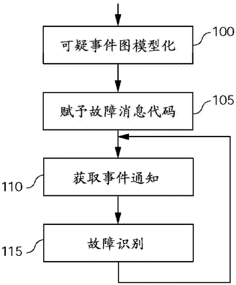
[0040] In general, the present invention is directed to a diagnostic assistance system for an aircraft system that uses graphs of suspicious events (or "failure condition graphs" in English terminology), here based on fault trees developed during safety studies (called "faulttree" in English terminology).

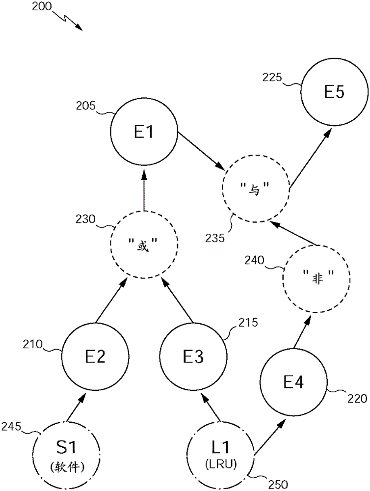
[0041] as in figure 1 As shown above, the overall approach is broken down here into four phases. The first phase (phase 100) is directed to the modeling of the graph of suspicious events. For an example of this type of modeling see figure 2 and image 3 to describe. The purpose of the second stage (stage 105) is to assign fault message codes to the pre-modeled graph of suspicious events. The third stage (stage 110 ) consists in obtaining the event detection notifications sent by the aircraft monitoring system in real time or time difference. Finally, in a fourth stage (stage 115 ), fault identification algorithms are executed by a machine, preferably automatically, t...


PUM


Abstract

The invention is particularly aimed at the diagnostic assistance of a system of an aircraft comprising a plurality of subsystems, at least one of which comprises monitoring and notification means of at least one event detected, using a graph of suspicious events. After receiving (500) a message notifying the realization of the detected event, creating (510) a group of suspicious events related to the message based on the graph of suspicious events, and according to the logical connections illustrated in the graph of suspicious events A logical expression is constructed (515) using system elements as operands and consistent with the suspicious events of said suspicious event group. A set of suspicious events is then created (520) based on the elements of the logical expression. Minimum collision sets of logical expressions associated with the set of suspicious events are computed, these minimum collision sets forming a diagnosis of the system.

Description

technical field [0001] The present invention relates to the diagnosis of components of complex systems, in particular aircraft complex systems, and more particularly to methods, devices and computer programs for assistance in diagnosis of aircraft systems using graphs of suspicious events. Background technique [0002] State-of-the-art diagnostic systems for diagnosing faults in aircraft typically use fault models designed by manufacturers and their equipment suppliers during the aircraft development cycle. [0003] For some manufacturers, these models are primarily developed by equipment manufacturers who develop monitoring systems for their equipment that include self-diagnostic software applications also known in English terminology as "Built-InTest Equipment" (BITE), Once the monitoring system detects a suspected faulty device, it reports a maintenance message for the suspected faulty device. The software application of the Centralized Maintenance System, known as CMS (...

Claims


Application Information

Patent Timeline
Patent Type & Authority Patents(China)
IPC IPC(8): G05B23/02
CPCG06F11/079G05B23/0248G06F11/0739G06F11/0748
Inventor V·谢里埃C·阿布兰J·罗歇L·维拉尔塔-埃斯特拉达
Owner AIRBUS OPERATIONS GMBH
Learn More