Relative displacement apparatus with light tractional force and high elastic attractive force

A technology of relative displacement and pushing force, which is applied in the direction of telephone structure, casing/cabinet/drawer parts, etc., and can solve the problems of semi-automatic elastic gravity, heavy gravity and inaccessibility

Inactive Publication Date: 2012-05-16
FIRST DOME
View PDF2 Cites 0 Cited by
  • Summary
  • Abstract
  • Description
  • Claims
  • Application Information

AI Technical Summary

Problems solved by technology

[0015] After observing the structures of the above various traditional relative displacement devices, it can be found that the elastic elements of these structures act on the displacement parts in a symmetrical form, that is, in all opening or closing displacement strokes, the operator The elastic force in the first half of the shift is gradually increased to the highest point in the center with the displacement. After passing the central turning point, the release of the elastic recovery force of the elastic elements is used to semi-automatically push the displacement member to the displacement. The end of the stroke is used to form a position, and the structure is still unable to achieve the function of a lighter driving force in the first half of the displacement, and a heavier semi-automatic elastic attraction in the second half; therefore, if these traditional structures are applied to smaller mobile phones, Handheld game consoles or personal digital assistants (PDAs) and other products have indeed achieved the practicability of ease of use. However, if they are directly applied to portable computers or increasingly popular tablet computers (such as Figure 9 to Figure 16 As shown), the weight of the relative displacement parts will increase due to the larger size of the product. When the weight of the displacement parts increases, the semi-automatic spring-attraction in the second half of the displacement process must increase to fully Therefore, it is relatively necessary to increase the elastic coefficient of the elastic element to adapt to the enlargement of the pulling object; and when the elastic coefficient of the elastic element increases, not only the cost of the manufactured element will increase, but it will inevitably As a result, the force applied by the operator to push the displacement parts in the first part of the displacement stroke will also increase, which will only increase the operating load, and if the elastic attraction force at the end of the displacement stroke is too large, the possibility of damage to the product and The adverse effect rate of the service life will inevitably increase accordingly; in this regard, it is necessary to improve

Method used


Image

  • Relative displacement apparatus with light tractional force and high elastic attractive force
  • Relative displacement apparatus with light tractional force and high elastic attractive force
  • Relative displacement apparatus with light tractional force and high elastic attractive force

Examples


Embodiment Construction

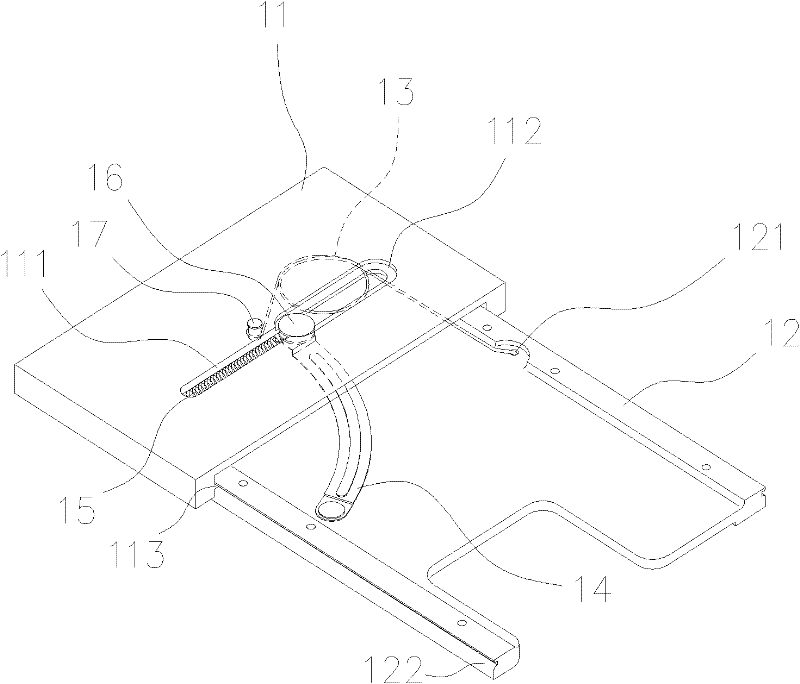
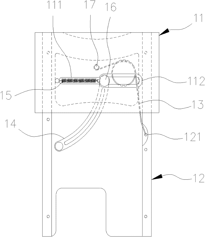
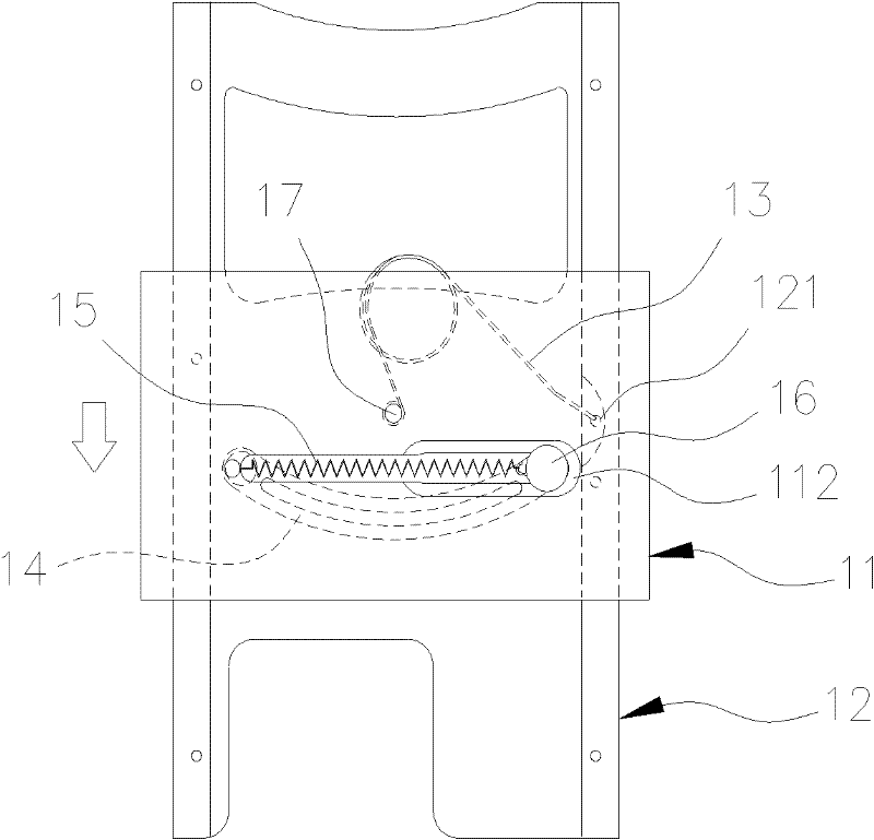
[0066] Such as Figure 17 to Figure 19 As shown, the present invention is a relative displacement device with both light pushing force and high elastic attraction, and mainly includes at least two displacement parts 50, 60 that can displace each other. Figure 17 The sliding cover 5 and its main body 6 of the electronic device shown; the two displacement parts 50, 60 are slidably combined with each other according to the preset translation rails 51, 61, so that they can be translated along one of the displacement parts 50 Surfaces 52 carry out mutual parallel displacement (as Figure 20A to Figure 21E shown); the translational surface 52 is provided with a main curvature displacement path 53 corresponding to the parallel displacement direction, and the main curvature displacement path 53 may have two displacement path endpoints 531, 532, and at the main curvature The path turning point 533 in the middle (point) of the variable displacement path 53 (it can be exactly located a...


PUM


Abstract

The invention discloses a relative displacement apparatus with a light tractional force and a high elastic attractive force. The relative displacement apparatus comprises at least two displacement members that are capable of making mutually parallel displacement. One of the displacement members is provided with a main deformation displacement path that is established and is corresponded to the translation direction of the displacement member; and at least one path turning point is arranged in the middle of the main deformation displacement path. The other displacement member is provided with an auxiliary deformation displacement path that is arranged towards an opposite direction and is corresponded with the main deformation displacement path; at least one displacement path end point is arranged at a correlated position on the auxiliary deformation displacement path, wherein the correlated position is corresponded to the position of the path turning point of the main deformation displacement path; and a spring and draw point is formed by intersection during the at least local continuous stroke of the main deformation displacement path and the auxiliary deformation displacement path. Besides, an elastic element is provided; one end of the elastic element can be slidablely pivoted and connected with the spring and draw point to form a spring and draw end; and the other end of the elastic element is fixedly pivoted and connected with the displacement member having the auxiliary deformation displacement path to form a fixed end.

Description

technical field [0001] The invention relates to a relative displacement device, in particular to a relative displacement device with light pushing force and high elastic attraction. Background technique [0002] With the rapid development of the electronic industry, the types and functions of portable electronic products are changing with each passing day, especially for electronic products such as mobile communication devices (telephones), portable computers, handheld game consoles, and personal digital assistants (PDAs). In the direction of development, in order to facilitate the use of operators, more and more attention has been paid to and increase the design of the human-machine interface. In order to achieve the purpose of increasing the range of interfaces that can be set without vainly expanding the overall area or volume of the product, it has been derived. The structural design of the opening and closing type of relative folding between the cover and the body (ie f...

Claims


Application Information

Patent Timeline
Patent Type & Authority Applications(China)
IPC IPC(8): H05K5/03H04M1/02
Inventor 买健诚
Owner FIRST DOME
Why Eureka
Try Eureka