
Suspension device with front and back torsion bars for automobile

A suspension device and rear suspension technology, applied in the direction of suspension, elastic suspension, vehicle components, etc., can solve the problems of restricting implementation, difficult implementation, complex structure, etc., and achieve the effect of improving shock absorption

Inactive Publication Date: 2012-05-23
李志东
View PDF3 Cites 3 Cited by
  • Summary
  • Abstract
  • Description
  • Claims
  • Application Information

AI Technical Summary

Problems solved by technology

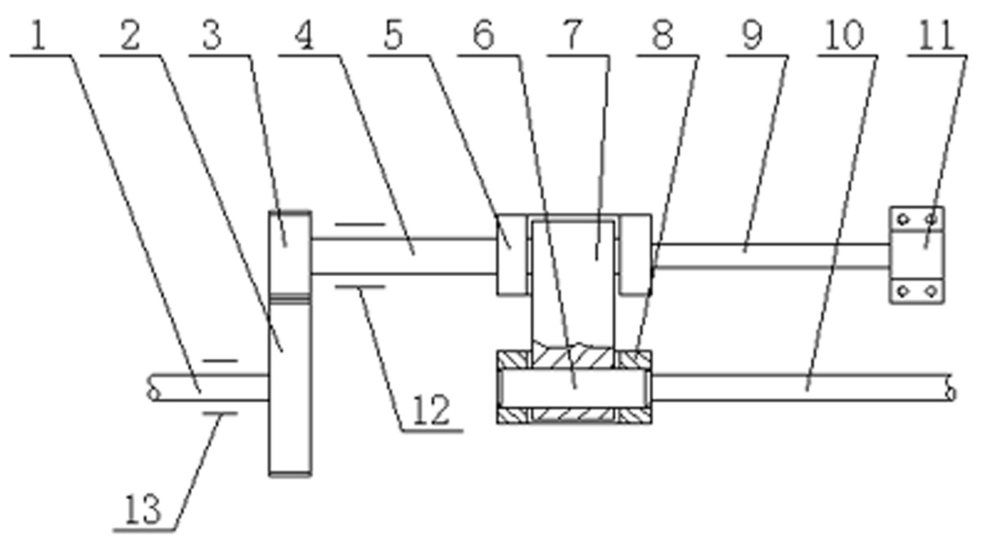
The patent application is to connect the front and rear torsion bar springs on the same side of the car to each other, and connect them to the frame through a positioning device, which can effectively improve the vibration of the car on uneven roads during driving. At the same time, the frame and body frame It will not be subjected to torsion, prolonging the service life of the vehicle, but due to the complex structure, it is difficult to implement, which restricts its implementation

Method used


Image

  • Suspension device with front and back torsion bars for automobile
  • Suspension device with front and back torsion bars for automobile
  • Suspension device with front and back torsion bars for automobile

Examples


Embodiment 1

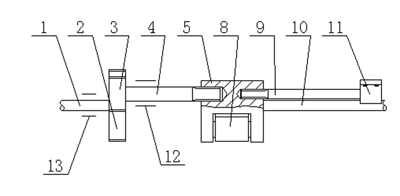
[0022] Such as figure 1 , 2 As shown, the left end of the front torsion bar spring 1 is connected with the control arm of the front suspension of the automobile, the right end of the front torsion bar spring 1 is fixedly equipped with the front torsion bar gear 2, and the force transmission gear 3 meshing with the front torsion bar gear is fixed on the The left end of the power transmission shaft 4 and the right end of the power transmission shaft 4 are fixedly installed on the connecting rod III5, and the reset torsion bar spring 9 is fixedly installed coaxially on the opposite side of the connecting rod III with the power transmission shaft, and the right end of the reset torsion bar spring It is fixedly installed on the vehicle frame through the fixing seat 11. The purpose of installing the reset torsion bar spring is to make the front torsion bar spring and the rear torsion bar spring reset quickly after torsional deformation.

Embodiment 2

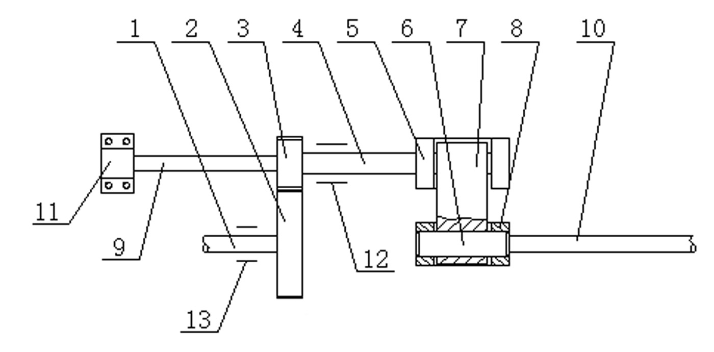
[0024] Such as image 3 As shown, on the basis of Embodiment 1, the installation position of the reset torsion bar spring 9 can be changed from being fixed on the connecting rod III5 to being fixedly connected with the power transmission gear 3, that is, the left end of the power transmission gear is fixedly connected with The reset torsion bar spring is fixedly connected with the power transmission shaft 4 at the right end of the power transmission gear, and the reset torsion bar spring is coaxial with the power transmission shaft.

Embodiment 3

[0026] Such as Figure 4 Said, the right end of rear torsion bar spring 10 is connected with the rear suspension of automobile, the left end of rear torsion bar spring 10 is fixedly installed with rear torsion bar gear 14, the left end of front torsion bar spring 1 is connected with the control arm of automobile front suspension, The right end of the front torsion bar spring 1 is fixedly connected on the connecting rod I8, and other structures are the same as in the first embodiment.


PUM


Abstract

The invention relates to a suspension device for an automobile, in particular to a suspension device with front and back torsion bars for an automobile. In the device, front and back torsion bar springs on the same side are mutually connected through a pair of meshed gears and a planar linkage mechanism; a linkage relation is established between the front and back torsion bar springs on the same side, so that the vibration condition of the automobile on uneven roads in the running process can be effectively improved, a frame and a body skeleton cannot be subjected to torsion, and the service life of the automobile is prolonged. The device has the characteristics of reasonable structure, good damping effect and the like.

Description

technical field [0001] The invention relates to an automobile suspension device, in particular to an automobile suspension device with front and rear torsion bars. Background technique [0002] In the current automobile suspension device, the torsion bar spring is generally installed on the front suspension device of the automobile, and the front and rear shock absorbing elastic elements of the automobile are independent and have no connection with each other, so that the spring will be in front of the automobile. 1. When the vibration direction of the rear wheels is opposite, the impact on the car will increase, and the body will fluctuate from front to back. The frame and body frame will be subject to a certain amount of torsion, resulting in reduced riding comfort, and the elastic elements are easily damaged, and the frame and body frame are easily deformed. In order to solve the above problems, the China Intellectual Property Office published an invention patent entitle...

Claims


Application Information

Patent Timeline
IPC IPC(8): B60G11/18B60G21/045
Inventor 李志东
Owner 李志东
Learn More