
Method, system and device for realizing intercommunication between two terminal nodes in different IP domains

A technology of terminal nodes and relay nodes, which is applied in the field of computer networks, can solve the problems of easy transmission, poor scalability, bottlenecks, etc., and achieve the effect of avoiding transmission bottlenecks and good scalability

Inactive Publication Date: 2015-11-11
CHINA MOBILE COMM GRP CO LTD
View PDF3 Cites 0 Cited by
  • Summary
  • Abstract
  • Description
  • Claims
  • Application Information

AI Technical Summary

Problems solved by technology

[0011] The embodiment of the present invention provides a method for realizing intercommunication between two terminal nodes in different IP domains, so as to solve the problems of poor scalability and easy occurrence of transmission bottlenecks in the prior art

Method used


Image

  • Method, system and device for realizing intercommunication between two terminal nodes in different IP domains
  • Method, system and device for realizing intercommunication between two terminal nodes in different IP domains
  • Method, system and device for realizing intercommunication between two terminal nodes in different IP domains

Examples


Embodiment 1

[0063] In this embodiment, the first terminal node UE1 in the IPv4 domain initiates a connection establishment request to request to establish a call connection with the second terminal node UE2 in the IPv6 domain. For the specific process of media communication between UE1 and UE2, please refer to the attached Figure 6 Shown:

[0064] Step 601, UE1 tries to communicate with UE2, and sends a domain name resolution request carrying UE2's identifier to DNS in the IPv4 domain where its local network is located;

[0065] Step 602, because the DNS in the IPv4 domain cannot resolve the IPv6 address of UE2, it returns an invalid domain name resolution response to UE1, for example, a domain name resolution response whose content is empty;

[0066] Step 603, because UE1 cannot obtain a valid domain name resolution result from the domain name resolution response, it determines that IPv4 and IPv6 interworking operations need to be performed, and proceeds to step 604;

[0067] Step 604...

Embodiment 2

[0108] In this embodiment, the first terminal node UE1 in the IPv6 domain initiates a connection establishment request to request to establish a call connection with the second terminal node UE2 in the IPv4 domain. For the specific process of media communication between UE1 and UE2, please refer to the attached Figure 8 Shown:

[0109] Step 801, UE1 tries to communicate with UE2, and sends a domain name resolution request carrying UE2's identifier to DNS in the IPv6 domain where its local network is located;

[0110] Step 802, because the DNS in the IPv6 domain cannot resolve the IPv4 address of UE2, it returns an invalid domain name resolution response to UE1, for example, a domain name resolution response whose content is empty;

[0111] Step 803, because UE1 cannot obtain a valid domain name resolution result from the domain name resolution response, it determines that IPv4 and IPv6 interoperability needs to be performed, and enters step 804;

[0112] Step 804, UE1 sends...


PUM


Abstract

The invention discloses a method for realizing intercommunication of two terminal nodes in different IP domains, a system and equipment thereof. In the prior art, expansibility is not good and a problem of transmission bottleneck is easy to be appeared. The method, the system and the equipment of the invention are used to solve the above problems. The method comprises: receiving a domain name analysis request sent by a first terminal node in a first IP domain and sending the domain name analysis request to a domain name server in a second IP domain so as to perform domain name analysis through a first relay node which is randomly selected; receiving a domain name analysis result correspondingly fed back by the domain name server in the second IP domain; selecting a second relay node based on a first IP domain address of the first terminal node and a second IP domain address of a second terminal node carried in the domain name analysis result so as to realize message conversion between the first terminal node and the second terminal node.

Description

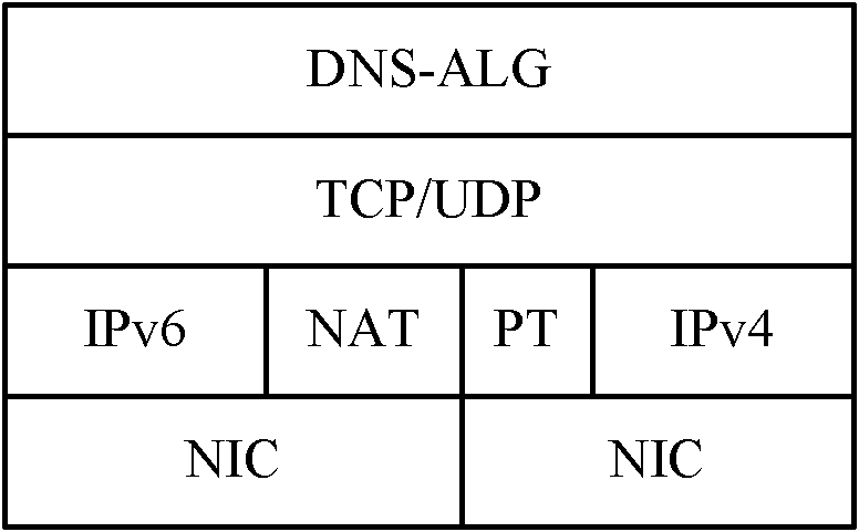
technical field [0001] The present invention relates to the technical field of computer networks, in particular to a method for realizing intercommunication between two terminal nodes in different IP domains, a system for realizing intercommunication between two terminal nodes in different IP domains, a relay server and a relay node device. Background technique [0002] A terminal device connected to the network needs to transmit messages with other terminal devices through the address assigned to the terminal device. With the increasing scale of the Internet Internet network, the number of terminal devices connected to the network is also increasing, and the existing IPv4 address resources are already very scarce. In order to solve this problem, the prior art proposes to assign temporary IPv4 addresses to terminal equipment or Network Address Translation (NAT, Network Address Translation) technology, although these technologies can alleviate the shortage of IPv4 addresses ...

Claims


Application Information

Patent Timeline
Patent Type & Authority Patents(China)
IPC IPC(8): H04L29/12H04L29/06
Inventor 彭晋乐利锋周乃宝
Owner CHINA MOBILE COMM GRP CO LTD
Learn More