Pivotable propeller nozzle for a watercraft

A propeller and nozzle technology, applied in ship propulsion, steering with jets, hull, etc., can solve problems such as connection instability, and achieve the effects of low material cost, high bending moment, and good torsional rigidity

Active Publication Date: 2012-05-23
BECKER MARINE SYST
View PDF8 Cites 5 Cited by
  • Summary
  • Abstract
  • Description
  • Claims
  • Application Information

AI Technical Summary

Problems solved by technology

This reinforcement, together with the complex flange connection through the reinforcement plate, is necessary because due to the interface between the relatively thin solid shaft and the hollow body of the nozzle ring (which has a correspondingly thin profile), the Produces noticeable problems and causes unstable connections

Method used


Image

  • Pivotable propeller nozzle for a watercraft
  • Pivotable propeller nozzle for a watercraft
  • Pivotable propeller nozzle for a watercraft

Examples


Embodiment Construction

[0070] In the different embodiments described in the following figures, the same constituent parts have the same reference numerals.

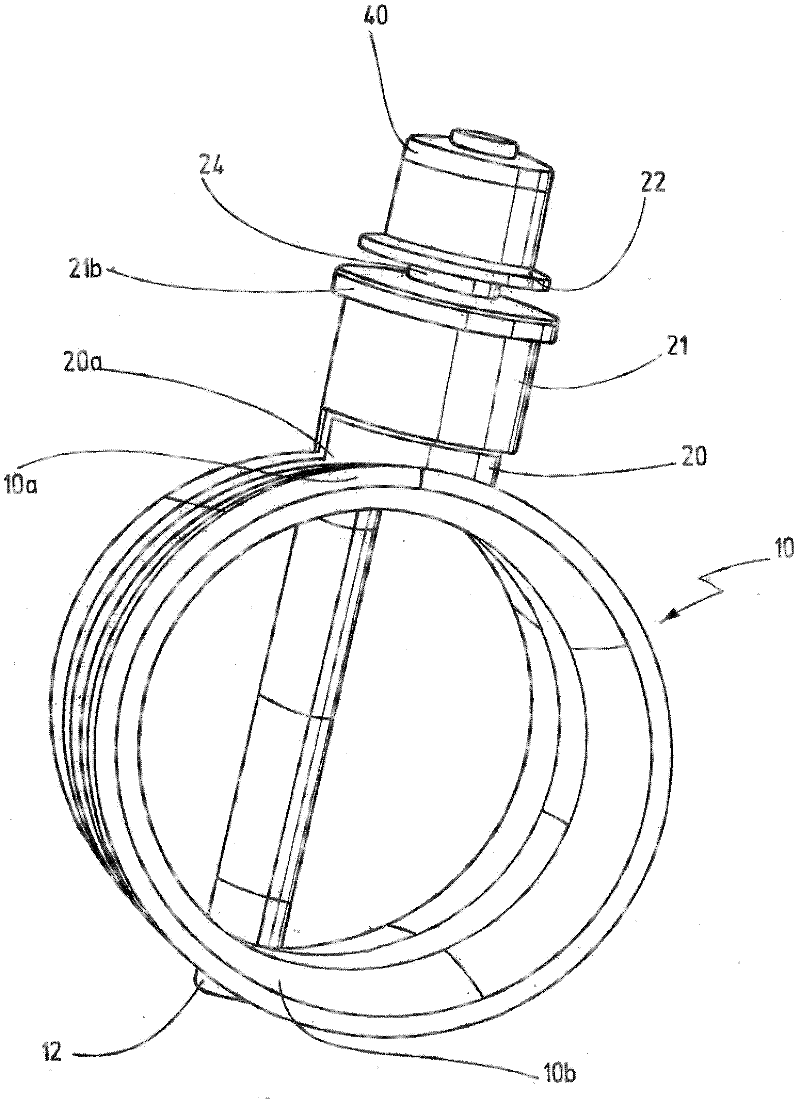
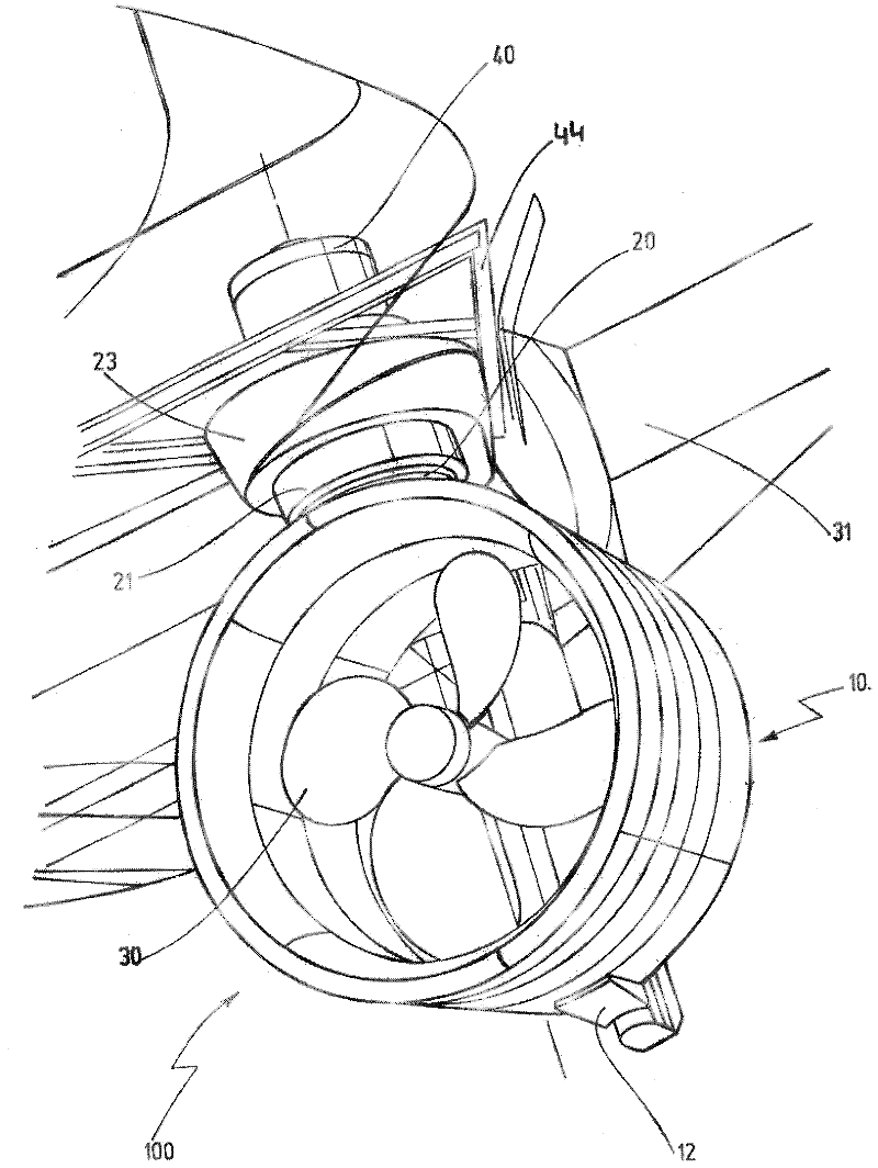
[0071] figure 1 A nozzle ring 10 of a propeller nozzle is shown, which has a nozzle shaft 20 designed as a hollow cylinder. To provide a better viewing angle, the propeller is omitted. exist figure 2 The same nozzle ring 10 is shown in the installed state (i.e. mounted on a vessel), i.e. in figure 2 The midship propeller 30 is arranged inside the nozzle ring 10 . In order to provide a better perspective, the figure 2 The propeller shaft is omitted in . Only the vessel body 31 of the vessel is shown in this region, ie in this region the nozzle stems are mounted at the same location. At the same time, the vessel body 31 is partly drawn transparent, so the swing drive 40 and its connection structure 44 on the vessel body 31 that is placed on the nozzle rod 20 and constitutes a rotating vane steering unit can be partially seen. The swing...


PUM


Abstract

In order to achieve a connection between a nozzle shaft (20) and a nozzle ring (10) that has the simplest design possible, while at the same time being stable, in a propeller nozzle (100) for a watercraft which comprises a fixed propeller (30) and a nozzle ring (10) surrounding the propeller (30), said nozzle ring being pivotable by means of a nozzle shaft (20), the nozzle shaft (20) is designed as a hollow body.

Description

technical field [0001] The present invention relates to a swingable propeller nozzle for ships and to a nozzle rod for swinging the propeller nozzle for ships. Background technique [0002] The drive unit of a ship, in particular a watercraft, is called a propeller nozzle and contains a propeller which is surrounded or shrouded by a nozzle ring. Such nozzle rings are also known as "Kort nozzles". The propellers arranged inside the nozzle ring are usually of fixed design, ie the propellers can only pivot about the drive axis or the propeller axis. For this purpose, the propeller is connected to the main body of the vessel via a rotatable but non-pivotable propeller shaft extending along the propeller axis. The propeller shaft is driven by a drive provided in the body of the boat. In contrast, propellers are not oscillating (horizontally or vertically). [0003] In the case of a simple structure of the propeller nozzle, the nozzle ring surrounding the propeller is also fix...

Claims


Application Information

Patent Timeline
Patent Type & Authority Applications(China)
IPC IPC(8): B63H5/14
CPCB63B3/40B63H5/15B63H25/34B63H25/46B63H5/14
Inventor 迪克·莱曼
Owner BECKER MARINE SYST
Why Eureka
Try Eureka