Door comprising drive system

A drive system, door leaf technology, used in manufacturing tools, door/window accessories, multi-purpose hand tools, etc., can solve problems such as cost and high structure, achieve high functional safety, simple structure, and prevent rope breakage.

Inactive Publication Date: 2012-05-23
SOMMER ANTRIEBS & FUNKTECHNIK GMBH
View PDF8 Cites 2 Cited by
  • Summary
  • Abstract
  • Description
  • Claims
  • Application Information

AI Technical Summary

Problems solved by technology

[0005] The disadvantage here, however, is that the individual cables of the cable unit involve an undesirably high structural complexity.
It is particularly disadvantageous that a separate fastening mechanism must be provided on its free end for each rope

Method used


Image

  • Door comprising drive system
  • Door comprising drive system
  • Door comprising drive system

Examples


Embodiment Construction

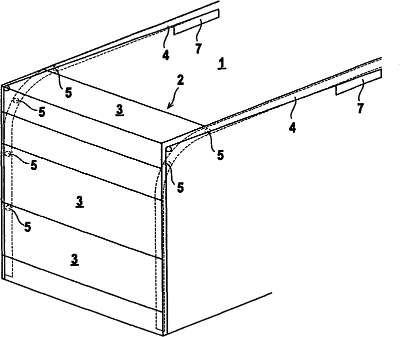
[0025] figure 1 An exemplary embodiment of a door 1 , in particular a ceiling door, is shown, which has a door leaf 2 formed from a multiple arrangement of panels 3 articulated to one another.

[0026] The door leaf 2 of the door 1 is guided laterally in guide rails which are installed in a building, in this example a garage.

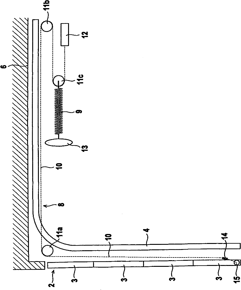
[0027] Such as figure 1 As shown in , the opening of the garage can be closed with the door leaf 2 of the door 1 . In the closed state of the door 1 , the door leaf 2 is situated in the region of the section of the guide rail 4 extending in the vertical direction. In the open state of the door 1 , the door leaf 2 is located in the region of the section of the guide rail 4 that extends in the horizontal direction below the garage ceiling. Guide rollers 5 are arranged on the door leaf 2 in both side edges, said guide rollers being guided in the guide rails 4 .

[0028] In order to open and close the door 1, a drive system (not shown) is provided. The...


PUM


Abstract

The invention relates to a door (1) comprising a drive system by means of which a door leaf (2) can be moved between an open position and a closed position, said door leaf being laterally guided in guide rails. A weight compensation device comprises a cable unit (8) and a spring unit (9) on one or each side of the door leaf, as well as a cable tension compensation device (12) associated with the cable unit (8). The or each cable tension compensation device (12) is protected against cable breakage. The or each cable unit (8) consists of one cable (10) which is deflected in the cable tension compensation device (12), said device being fixed in place, such that two cable strands are obtained which run at a distance from each other. The free ends of the cable (10) are guided together and fixed to the door leaf (2). Alternatively, the cable tension compensation device (12) can be fixed to the door leaf (2). In this case the free ends of the cable (10) are fixed in place.

Description

technical field [0001] The invention relates to a door with a drive system according to the preamble of claim 1 . Background technique [0002] Such a door is known from DE 0 890 010 B1. The door described in this document has a door leaf that is guided laterally in guide rails and can move downwards, which can be moved between a closed position and an open position by means of a drive system. In order to compensate for the weight of the door leaf, a weight compensation device is provided which secures the door leaf in any position so that, for example, in the event of a failure of the drive system, an uncontrolled falling of the door leaf is prevented. [0003] The weight compensation device has on each side of the door leaf a cable unit extending in the region of the respective guide rail, which cable unit has a spring unit in the horizontal section of the guide rail. In this case, each string unit comprises two parallel running strings which are guided onto the spring u...

Claims


Application Information

Patent Timeline
Patent Type & Authority Applications(China)
IPC IPC(8): E05D15/24E05D13/00
CPCE05Y2800/21E05Y2201/67E05Y2800/246E05Y2600/11E05D13/003E05Y2900/106E05Y2800/205E05D15/24E05D13/1223E05D13/1215E05Y2201/654E05Y2800/242
Inventor G·沙夫
Owner SOMMER ANTRIEBS & FUNKTECHNIK GMBH
Why Eureka
Try Eureka