Shock absorbing structure and method of manufacturing same
A shock absorption and manufacturing method technology, applied in the direction of additive manufacturing, manufacturing tools, prostheses, etc., can solve the problem of low shock absorption and achieve the effect of low Young's modulus and excellent shock absorption
- Summary
- Abstract
- Description
- Claims
- Application Information
AI Technical Summary
Problems solved by technology
Method used
Image
Examples
no. 1 Embodiment approach
[0060] Structure of shock absorbing structure
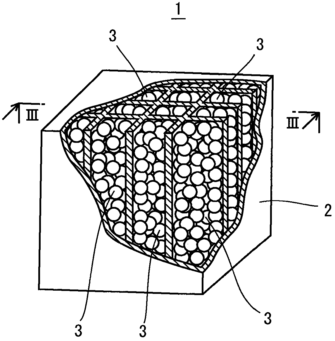
[0061] figure 1 It is a perspective view of the shock-absorbing structure of this embodiment. refer to figure 1 , the shock absorbing structure 1 has a solidified member 2 and a plurality of sintered members 3 .
[0062] The solidified member 2 is formed by melting a plurality of inorganic powder particles and solidifying after melting. Inorganic powder particles are powder particles composed of inorganic substances. Inorganic powder particles are, for example, metal or intermetallic compounds, ceramics, and the like. Metals are pure metals or alloys. Preferably the inorganic powder particles are metal.
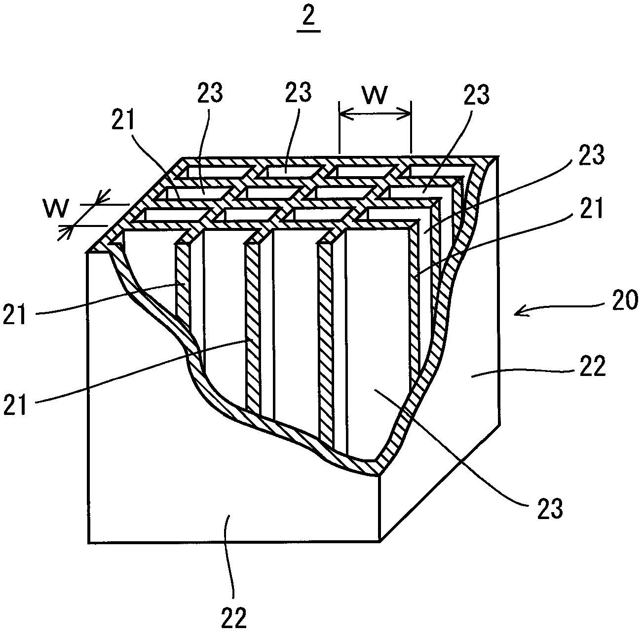
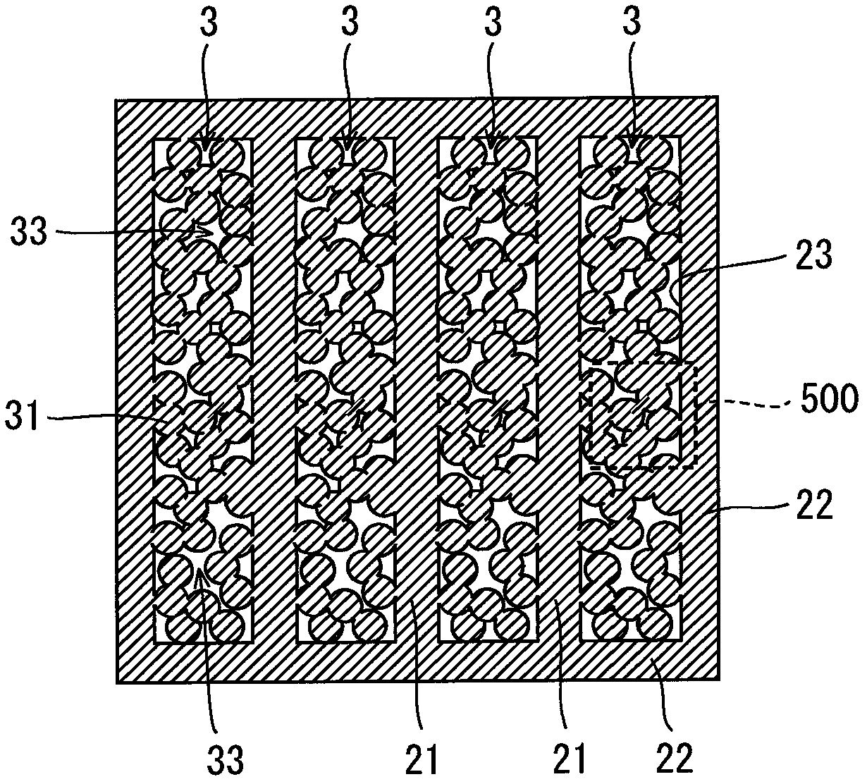
[0063] figure 2 A perspective view of the coagulation member 2 is shown in . The solidification member 2 includes a solidification shell 20 and a plurality of solidification walls 21 . The solidification shell 20 has a plurality of solidification walls 22 . That is, the solidified wall 22 corresponds to the outer wa...
no. 2 Embodiment approach
[0151] The shock absorbing structure is not limited to figure 1 , Figure 22A , Figure 23A structure shown. Figure 24 It is a perspective view of the shock absorbing structure 150 of the second embodiment. Figure 25 yes Figure 24 XXV-XXV sectional view in. refer to Figure 24 and Figure 25 , the shock-absorbing structure 150 has the solidified member 2 and the sintered member 3 similarly to the shock-absorbing structure 1 and the shock-absorbing structure 100 . The solidification member 2 is rod-shaped and solid. The sintered component 3 is arranged around the axis of the solidified component 2 . That is, the sintered member 3 is a cylindrical body, and the solidified member 2 is inserted therein. The sintered component 3 is combined with the solidified component 2 .
[0152] An example of a method of manufacturing the shock-absorbing structure 150 will be described below. Figure 26 It is a flowchart showing an example of a method of manufacturing the shock-ab...
PUM
| Property | Measurement | Unit |
|---|---|---|
| particle diameter | aaaaa | aaaaa |
| particle size | aaaaa | aaaaa |
| porosity | aaaaa | aaaaa |
Abstract
Description
Claims
Application Information
 - R&D
- Intellectual Property
- Life Sciences
- Materials
- Tech Scout
- Unparalleled Data Quality
- Higher Quality Content
- 60% Fewer Hallucinations
Browse by: Latest US Patents, China's latest patents, Technical Efficacy Thesaurus, Application Domain, Technology Topic, Popular Technical Reports.
© 2025 PatSnap. All rights reserved.Legal|Privacy policy|Modern Slavery Act Transparency Statement|Sitemap|About US| Contact US: help@patsnap.com


