Lip type seal element
A technology of lip seals and sealing components, which is applied to engine seals, pump components, bearing components, etc., and can solve problems such as sealing lip 82 foaming and sealing performance degradation
- Summary
- Abstract
- Description
- Claims
- Application Information
AI Technical Summary
Problems solved by technology
Method used
Image

Examples
no. 1 example
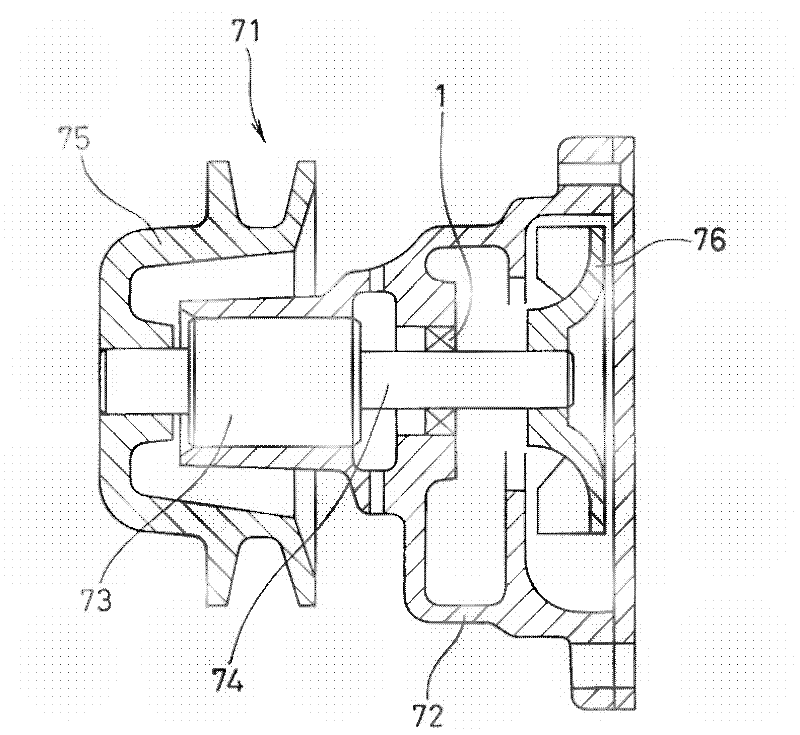
[0092] figure 1 An overall view showing a water pump 71 to which a lip seal 1 according to an embodiment of the present invention is mounted, that is, on one end of a shaft (rotation shaft) 74 rotatably supported by a housing (casing) 72 via a bearing 73 A pulley 75 is fixed, and an impeller 76 is fixed on the other end. When the driving torque is transmitted to the pulley 75, the impeller 76 rotates to pressure-feed cooling water. The lip seal 1 is attached to the inner periphery of the shaft hole of the housing 72 and is slidably in close contact with the peripheral surface of the shaft 74, thereby suppressing leakage of the sealing fluid (cooling water) in the machine to the atmosphere side (bearing side).
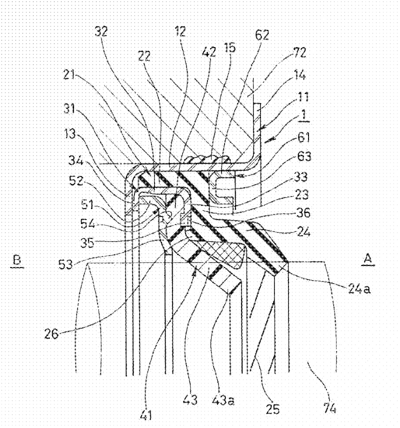
[0093] figure 2 A cross section of a main part of the lip seal 1 according to the first embodiment is shown, and the lip seal 1 is configured as follows. The right side of the figure is the seal fluid side A, and the left side of the figure is the atmospheric side B...
no. 2 example
[0119] In addition, in the above-mentioned first embodiment, the flange portion 13 of the sleeve 11 and the second flange portion 34 of the housing 31 abut against each other in the axial direction. A phenomenon in which an assembly composed of the resin-made second lip seal member 41 , the backup ring 51 , and the housing 31 slides and co-rotates with the shaft 74 . As a second embodiment, Figure 4 Such an anti-rotation structure is provided, that is, on the inner peripheral edge portion of the flange portion 13 of the sleeve 11, a part of the claw portion 16 on the circumference is provided, and at the same time, corresponding to the claw portion 16, a second protrusion on the housing 31 is provided. A notch 37 is provided on the inner peripheral portion of the edge 34 , and the sleeve 11 and the housing 31 are prevented from rotating when the claw 16 is bent toward the sealing fluid side A and engaged with the notch 37 . The claw portion 16 and the notch portion 37 are di...
no. 3 example
[0122] That is, in the first embodiment described above figure 2 In, a one-way thread structure is formed with respect to the threaded portion 25, and in the third embodiment shown as Figure 5 Among them, the threaded part 25 forms a two-way thread structure, that is, a plurality of threads (unit threads) 25a in the forward direction and threads in the opposite direction (unit threads) 25a in which the inclination directions (inclination directions of the threads) form opposite directions are alternately arranged on the circumference. ) 25b. Usually, the rotation direction of the shaft 74 is determined according to the model of the pump. Therefore, even if the threaded part 25 has a unidirectional structure, it can fully function. , The threaded portion 25 is preferably a bidirectional thread structure, so as long as the threaded portion 25 is a bidirectional thread structure, it can handle the situation that the shaft 74 rotates in any direction.
PUM
 Abstract
Description
Claims
Application Information
 - R&D Engineer
- R&D Manager
- IP Professional
- Industry Leading Data Capabilities
- Powerful AI technology
- Patent DNA Extraction
Browse by: Latest US Patents, China's latest patents, Technical Efficacy Thesaurus, Application Domain, Technology Topic.
© 2024 PatSnap. All rights reserved.Legal|Privacy policy|Modern Slavery Act Transparency Statement|Sitemap