Optical line termination, PON system, and data reception processing method
An internal device and data technology, applied in the field of in-station devices, can solve the problems of long preparation period and waste of frequency band, and achieve the effect of shortening the preparation period
- Summary
- Abstract
- Description
- Claims
- Application Information
AI Technical Summary
Problems solved by technology
Method used
Image

Examples
Embodiment approach 1
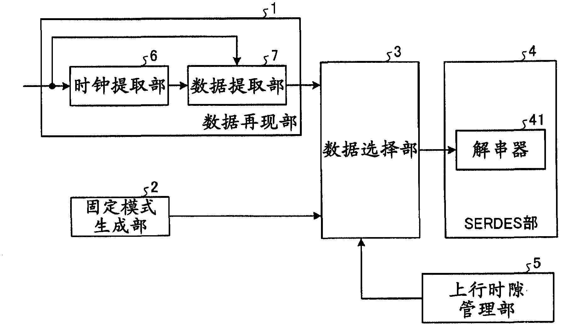
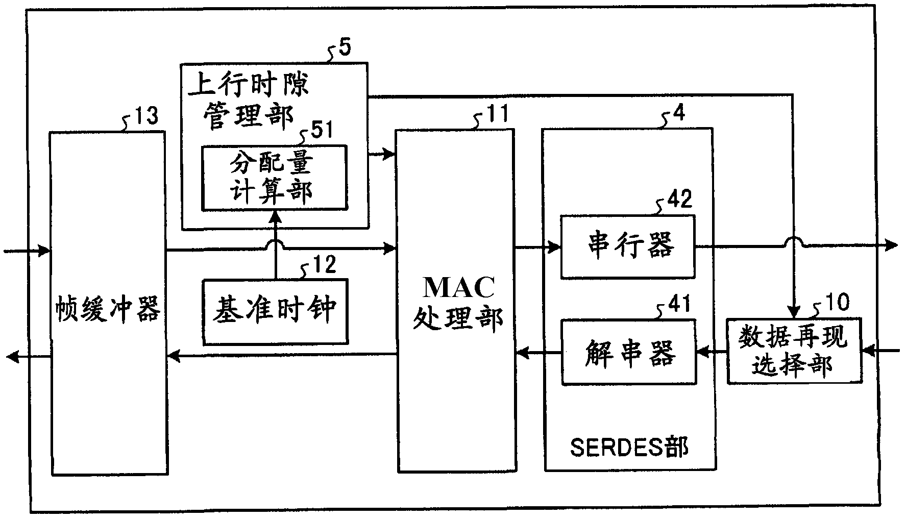
[0030] figure 1 It is a diagram showing an example of the functional configuration of the first embodiment of the on-site device (OLT) according to the present invention. The OLT of this embodiment is connected to a plurality of ONUs via optical couplers and optical fibers. figure 1 Indicates constituent elements that implement operations of the data processing method according to the present invention. like figure 1 As shown, the OLT of this embodiment includes: a data reproducing unit 1 that extracts a clock from data (burst data) intermittently received from the ONU and reproduces the data; a fixed pattern generating unit (data generator or pattern signal generator) 2 , generate fixed data; data selector (data selector) 3, decide output data according to the presence or absence (reception period) of the burst data of receiving; SERDES part 4; And upstream time slot management part 5, has the sending The function of timing is to control the access of PON, judge whether th...
Embodiment approach 2
[0055] Figure 8 It is a diagram showing an example of a functional configuration of Embodiment 2 of an on-site device (OLT) according to the present invention. like image 3 As shown, the in-station device of the present embodiment is the same as the in-station device of the first embodiment except that the uplink slot management unit 5a of the first embodiment is replaced with the uplink slot management unit 5 of the first embodiment, and a block synchronization detection unit 8 is added. Components having the same functions as those in Embodiment 1 are denoted by the same symbols as in Embodiment 1, and description thereof will be omitted.
[0056] This embodiment differs from Embodiment 1 in that a burst end instruction signal is output from the block synchronization detection unit 8 . Other operations of this embodiment are the same as those of the first embodiment. Figure 9 It is a figure which shows an example of the operation|movement of this embodiment. in additi...
Embodiment approach 3
[0063] Figure 11 It is a diagram showing an example of the functional configuration of the third embodiment of the on-site device (OLT) according to the invention. like Figure 5 As shown, the in-station device of this embodiment is the same as the in-station device of the second embodiment except that the block synchronization detection unit 8 of the second embodiment is provided inside the data selection unit 3a, and the data selection unit 3 is replaced by the data selection unit 3a. Components having the same functions as in Embodiment 1 or Embodiment 2 are given the same symbols as in Embodiment 1 or Embodiment 2, and descriptions thereof are omitted.
[0064] In the present embodiment, similarly to Embodiment 2, the data selection unit 3a is switched based on the burst end instruction signal output from the block synchronization detection unit 8, but the block synchronization detection unit 8 is set as an internal part of the data selection unit 3a. Function. With su...
PUM
 Abstract
Description
Claims
Application Information
 - R&D Engineer
- R&D Manager
- IP Professional
- Industry Leading Data Capabilities
- Powerful AI technology
- Patent DNA Extraction
Browse by: Latest US Patents, China's latest patents, Technical Efficacy Thesaurus, Application Domain, Technology Topic.
© 2024 PatSnap. All rights reserved.Legal|Privacy policy|Modern Slavery Act Transparency Statement|Sitemap