
Camera for a vehicle

A camera and vehicle technology, applied in vehicle parts, image communication, computer parts, etc., can solve problems such as significant device cost, and achieve the effect of not tolerant of depth of field fluctuations and simple installation

Inactive Publication Date: 2012-05-23
ROBERT BOSCH GMBH
View PDF6 Cites 6 Cited by
  • Summary
  • Abstract
  • Description
  • Claims
  • Application Information

AI Technical Summary

Problems solved by technology

However, considerable equipment outlay is necessary due to additional convex mirrors or other optics, for example external or arranged in front of the camera lens

Method used


Image

  • Camera for a vehicle
  • Camera for a vehicle
  • Camera for a vehicle

Examples


Embodiment Construction

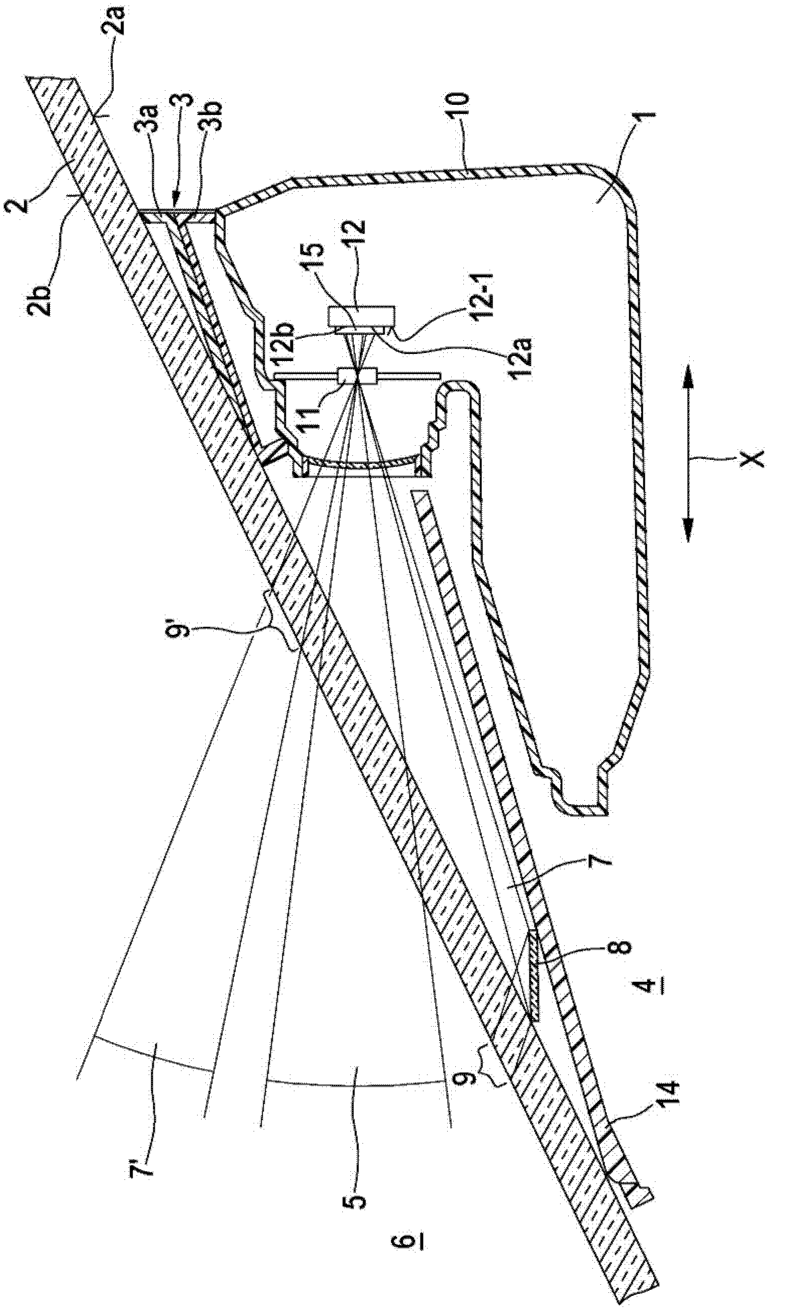
[0033] according to figure 1 , the camera 1 is applied to the window inner side 2 a of the vehicle window 2 . For this purpose, a camera holding device 3 is provided, which makes it possible to adjust the camera 1, for example, in the longitudinal direction of the vehicle, ie in the X direction of the vehicle, or also in a direction slightly deviating from the longitudinal direction of the vehicle, for example also in the X-Z plane, wherein Z is Vertical direction or vehicle height direction. exist figure 1 For this purpose, the outer holding frame 3a fixed on the vehicle window 2 and the frame inner part 3b adjustable in said outer holding frame are schematically shown, said outer holding frame 3a and frame inner part 3b together forming a holding frame 3. It is important that the camera 1 can be adjusted not only parallel to the window 2 but also non-parallel to the window 2 . The vehicle window 2 can be in particular a front window, but also a rear window, for example. ...


PUM


Abstract

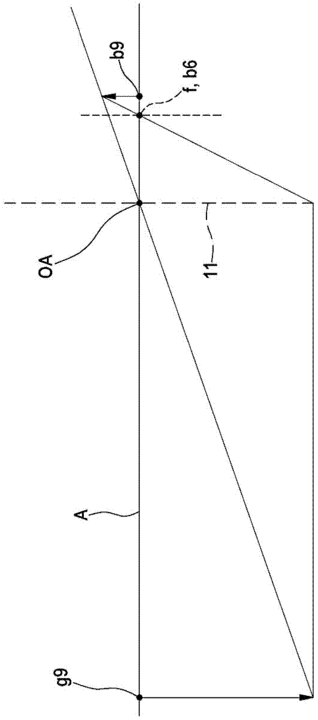
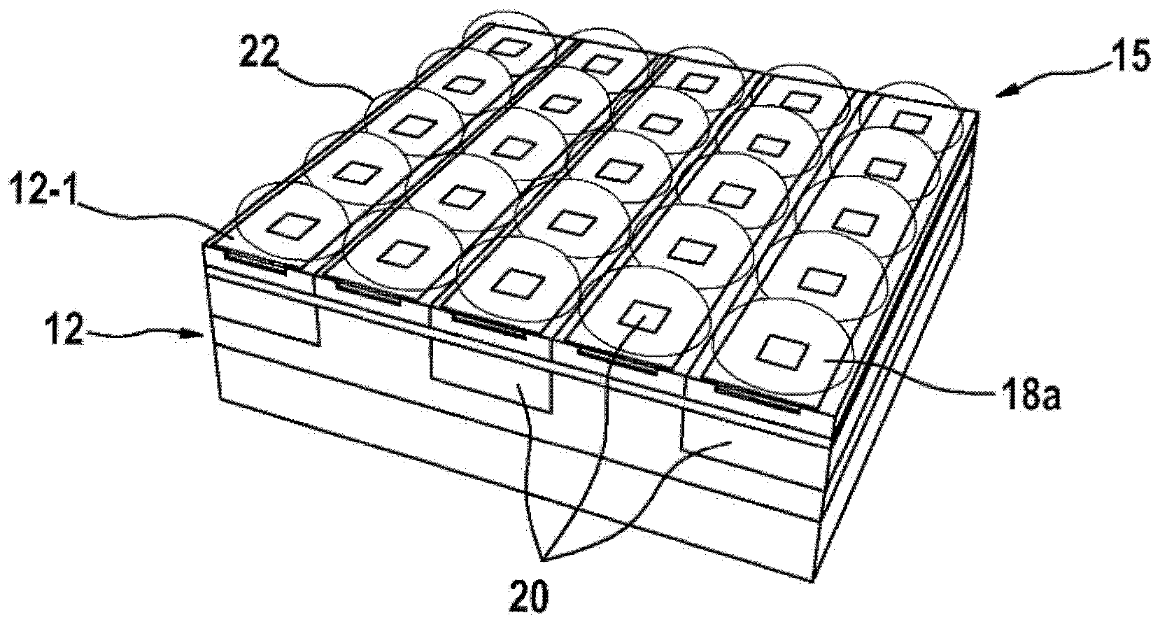
The invention relates to a camera for a vehicle, in particular for monitoring the exterior, wherein the camera (1) comprises: an imager (12) having a plurality of pixels (18a, 18b) and different imager regions (12a, 12b) for different object distances (g9, g6), and a lens (11) arranged in front of the imager (12). According to the invention, an additional optical unit (15) is provided between the lens (11) and the imager (12), said unit comprising in particular optical micro-elements, for example micro-lenses, wherein the additional optical unit (15) has different imaging properties for the imager regions (12a, 12b) of the imager (12), in particular for compensating different object distances and / or image distances.

Description

Background technique [0001] Video systems in vehicles are used in particular to implement different primary driver assistance systems, such as night vision systems, warning video systems, lane recognition, light assistance, etc. In this case, the camera detects the surroundings of the vehicle through the windows, in particular the front windows. Here, the object distance is generally set to infinity. Other regions with a limited object distance are therefore not imaged sharply in any case. [0002] Furthermore, cameras are known for secondary functions, such as the detection of raindrops on the outside of a window, for which light in general and in particular IR radiation impinges on the window and is detected by the imager of the camera. In this case, a separate imager region can be provided for this radiation. However such systems require vehicle-specific or window-specific overhead. [0003] US 2007 / 0096010 A1 shows a multifunctional optical sensor as a CCD element or C...

Claims


Application Information

Patent Timeline
Patent Type & Authority Applications(China)
IPC IPC(8): H04N5/232B60R1/00
CPCB60R11/04H04N5/23212H04N5/2254H01L27/14627H01L27/14645G06V20/56H04N23/55
Inventor M·卡尔
Owner ROBERT BOSCH GMBH
Learn More