Zoom lens system

a zoom lens and lens technology, applied in the field of optical lens systems, can solve the problems of reducing optical power, impracticality large and difficult to correct, large front group, etc., and achieve the effects of wide zoom range of focal lengths, high performance characteristics, and high performance zoom

Inactive Publication Date: 2007-05-29
COURTLAND CAPITAL MARKET SERVICES LLC +1
View PDF21 Cites 39 Cited by
  • Summary
  • Abstract
  • Description
  • Claims
  • Application Information

AI Technical Summary

Benefits of technology

[0011]General Summary of the Invention. It is an object of the present invention to provide a zoom lens system that overcomes the problems and inefficiencies of prior zoom lens systems having large zoom ratios. A further object is to provide a zoom lens system with a wide zoom range of focal lengths and high performance characteristics for both indoor and outdoor use. A still further object of this invention is to provide a zoom lens system with a ratio of about 300 to 1 and a zoom range, for example, from about 7 mm to 2100 mm focal length, with continuous zooming between the focal lengths. Still another object of this invention is to provide a high performance zoom lens system with an optical system having a front zoom lens group for forming an intermediate image and a rear zoom lens group to magnify that image to thereby produce an extremely large zoom ratio. Still another object is to provide such a zoom lens system with optical image stabilization. Still another object is to provide such a zoom lens system with a focusing lens group capable of precise focusing over the entire focal length range of the zoom ratio.
[0014]Summary of the Zoom Ratio Aspects of the Invention. The present invention overcomes the obstacles that currently limit zoom lens systems to a zoom ratio of about 101:1. The basic idea of the invention can be viewed as the use of a compound zoom lens system that consists of two separate zoom lens portions wherein the front zoom lens portion forms an intermediate image, and the rear zoom lens portion is a relay that transfers the intermediate image formed by the front zoom lens portion to the final image. The total zoom ratio of the complete compound zoom lens system is equal to the zoom ratio of the front zoom lens multiplied by the zoom ratio of the relay. Thus, if the zoom ratio of the front zoom lens portion is 20:1 and the zoom ratio of the relay is 15:1, then the zoom ratio of the entire compound zoom lens system is 300:1. The present invention can be used to achieve a zoom ratio of 300:1 or more, which greatly exceeds the practical limit of conventional zoom lens systems.

Problems solved by technology

As the zoom ratio is extended to about 100:1, however, the variator is required to change its object magnification to such an extent during zooming that aberrations become impracticably large and difficult to correct.
In addition, at such large zoom ratios there is a very large change in entrance pupil location during zooming, and this tends to make the front group very large and difficult to correct.
Another problem derives from the fact that, to reduce the aberration change that results from a large change of magnification, it is desirable that the variator have reduced optical powers.
Weaker optical power, however, also increases the lens travel and length of the optical system.
Since the requirements for either the front or the rear of the lens system can be satisfied, but not simultaneously, this results in no ideal place for the aperture stop.

Method used


Image

  • Zoom lens system
  • Zoom lens system
  • Zoom lens system

Examples


Embodiment Construction

[0030]In the following description of preferred embodiments, reference is made to the accompanying drawings, which form a part hereof, and in which is shown by way of illustration specific embodiments in which the invention may be practiced. It is to be understood that other embodiments may be utilized and structural changes may be made without departing from the scope of the preferred embodiments of the present invention.

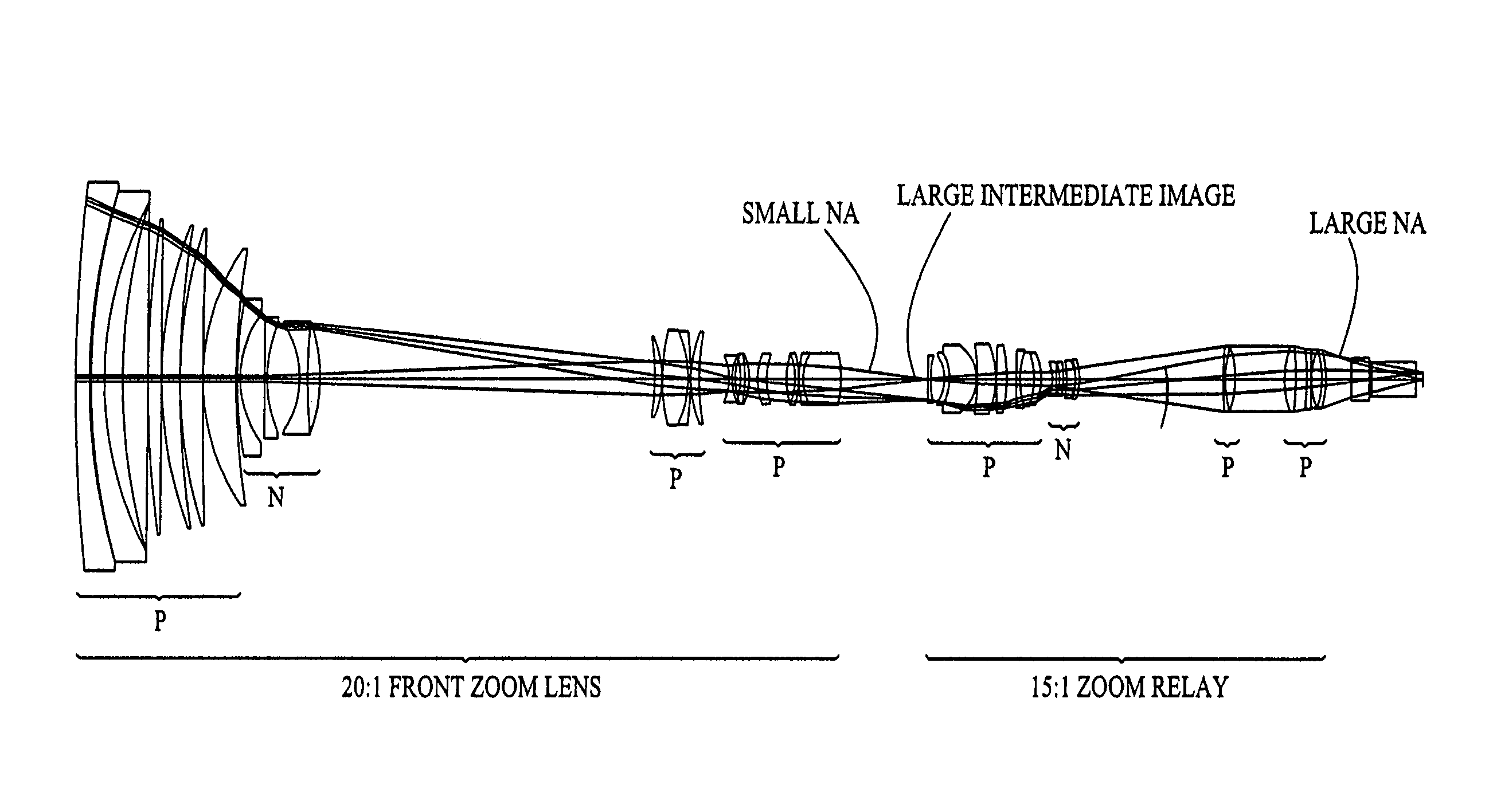
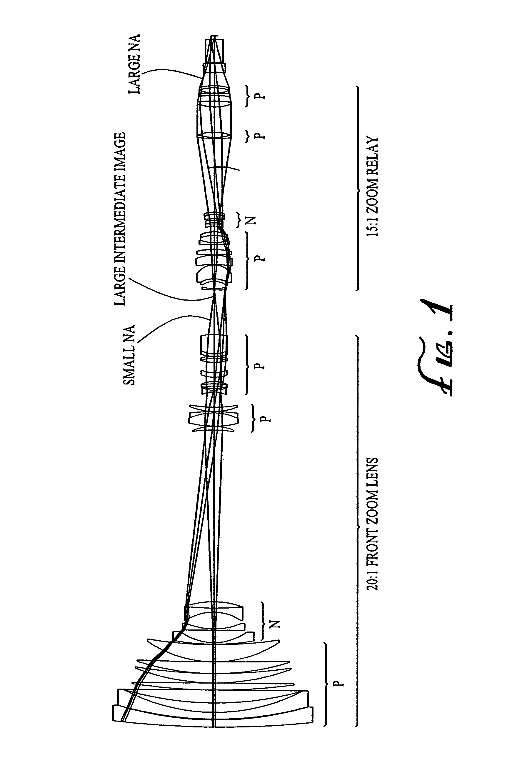
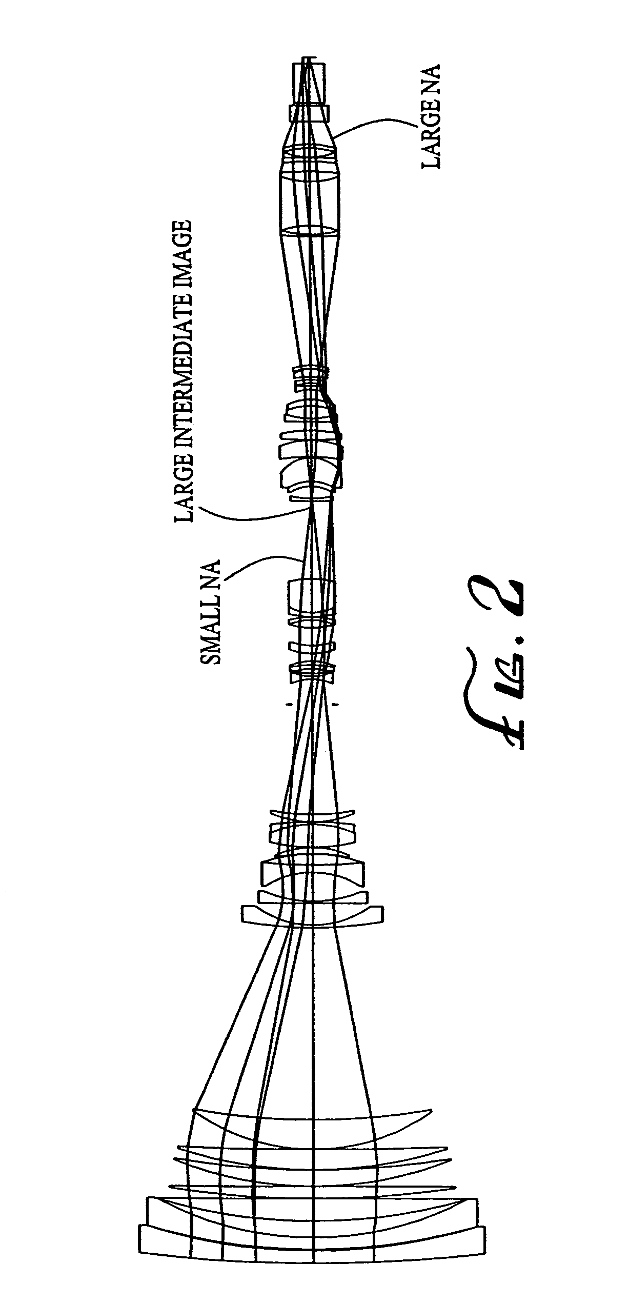
[0031]In accordance with its general aspects, the invention provides a zoom lens system for forming a final image of an object, said system forming a first intermediate real image between the object and the final image, said system comprising:

[0032](a) a first optical unit (e.g., lens elements 8 through 15 in FIG. 10) located between the object and the first intermediate real image, said unit comprising at least one optical subunit which is moved to change the size (magnification) of the first intermediate real image (e.g., lens elements 8 through 11 are the primar...


PUM


Abstract

A zoom lens system is disclosed. The zoom lens system forms a final image of an object and a first intermediate real image between the object and the final image. The zoom lens system includes a first optical unit located between the object and the first intermediate real image. The first optical unit comprises at least one optical subunit which is moved to change the size (magnification) of the first intermediate real image. The zoom lens system also includes a second optical unit located between the first intermediate real image and the final image, at least a portion of which is moved to change the size (magnification) of the final image. The zoom lens system provides a wide zoom range of focal lengths with continuous zooming between the focal lengths.

Description

CROSS-REFERENCE TO RELATED APPLICATION[0001]This application is a Continuation-In-Part (CIP) application of U.S. patent application Ser. No. 10 / 622,914, filed Jul. 18, 2003 now U.S. Pat. No. 6,961,188, which claims the benefit of U.S. Provisional Application No. 60 / 397,882, filed Jul. 22, 2002, which application is specifically incorporated herein, in its entirety, by reference.BACKGROUND OF THE INVENTION[0002]1. Field of the Invention[0003]This invention relates to optical lens systems for cameras and other optical devices, and, in particular, to high performance zoom lens systems that produce a high quality image over a full zoom range of focal lengths and are capable of being provided with an extremely large zoom ratio.[0004]2. Description of Related Art[0005]General Background of the Invention. The use of zoom lens systems for all types of photography, such as broadcast television, high definition television (“HDTV”), advanced television (“ATV”), video camcorders, film cinematog...

Claims


Application Information

Patent Timeline
Patent Type & Authority Patents(United States)
IPC IPC(8): G02B15/14G02B13/14G02B15/16G02B15/173G02B27/64
CPCG02B13/14G02B15/12G02B15/14G02B15/173G02B27/646G02B15/142
Inventor NEIL, IAIN A.
Owner COURTLAND CAPITAL MARKET SERVICES LLC
Why Eureka
Try Eureka