Isolated type H-bridge drive device

A driving device and isolated technology, applied in the field of power supply, can solve the problems of multiple design costs, inability to share ground, and low product reliability, and achieve the effect of increasing performance and electrical characteristics, wide application range, and saving space

Active Publication Date: 2015-01-21
GUANGDONG VTRON TECH CO LTD
View PDF5 Cites 8 Cited by
  • Summary
  • Abstract
  • Description
  • Claims
  • Application Information

AI Technical Summary

Problems solved by technology

The two pipes of the lower bridge can share the ground, but the two pipes of the upper bridge cannot share the ground
The H-bridge circuit is mostly connected to a high-voltage circuit. Since the two tubes of the upper bridge cannot be connected to the ground, they are in a floating connection state, so the driving signal voltage needs to be raised or isolated from the ground. Especially, for DSP or FPGA as When driving the source, because the driving circuit is often grounded without raising the driving voltage, it cannot use the ground signal to directly drive the upper bridge arm of the H bridge.
Existing methods for increasing the driving voltage include the method of boosting the capacitor, and the method of using a BOOST circuit to boost the voltage. A dedicated chip can also be used to increase the driving voltage, and there is also a method of directly isolating the drive by using an isolation transformer. These methods Unfavorable factors will complicate the design of the drive circuit, increase the difficulty of the design, and are not conducive to mastering the results of the control design, resulting in lower reliability of the designed product and bringing more design costs.

Method used


Image

  • Isolated type H-bridge drive device
  • Isolated type H-bridge drive device

Examples


Embodiment Construction

[0013] The present invention will be further described below in conjunction with the accompanying drawings, but the embodiments of the present invention are not limited thereto.

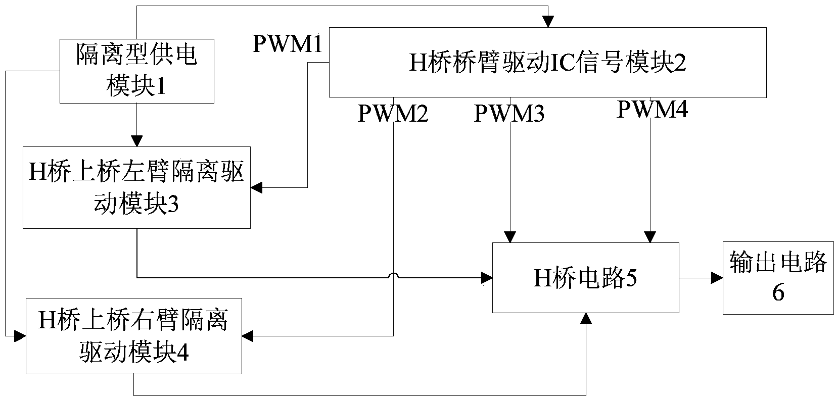
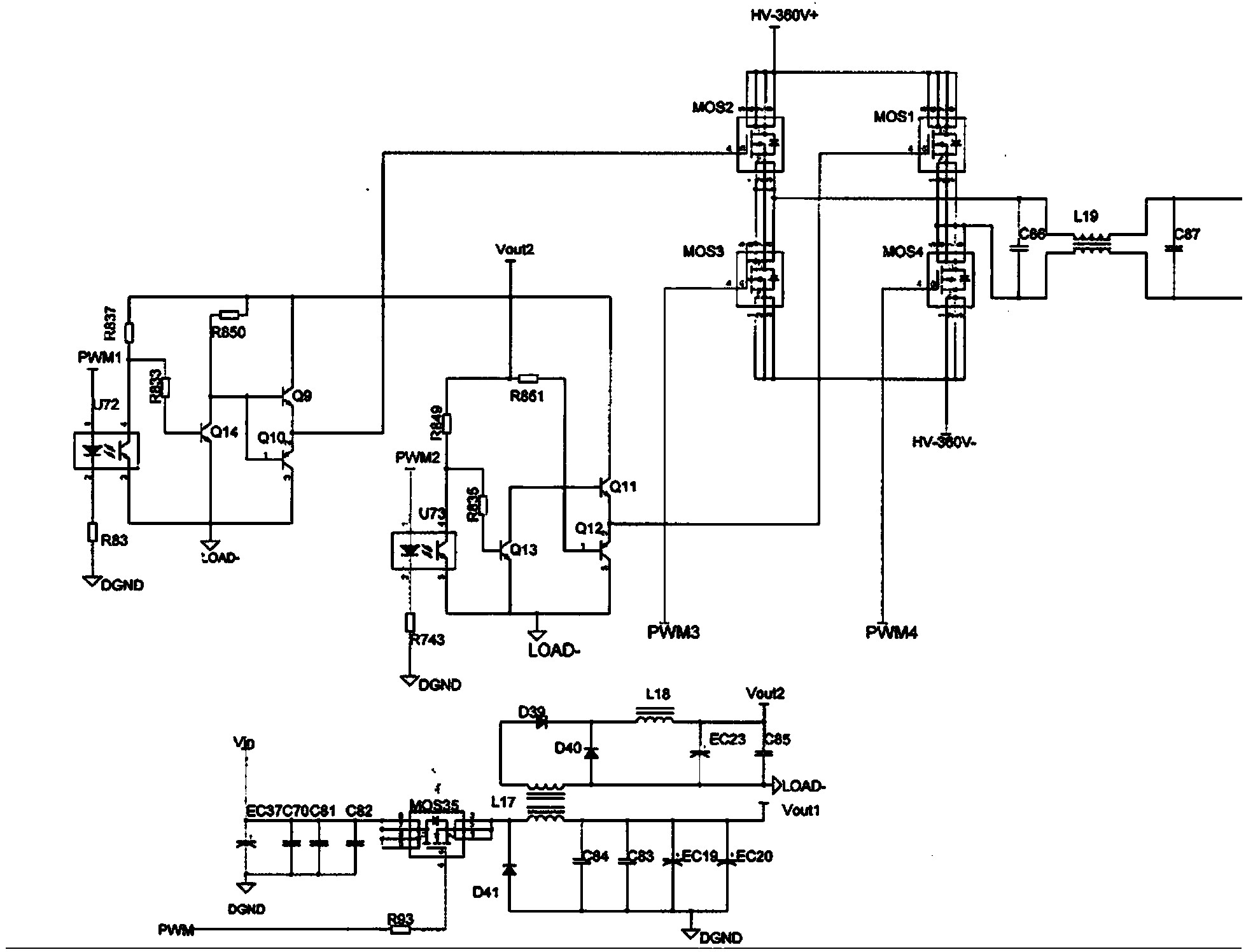
[0014] Such as figure 1 , 2 , an isolated H-bridge driving device, comprising an isolated power supply module 1, an H-bridge arm drive IC signal module 2, an isolated drive module 3 for the left arm of the upper bridge of the H bridge, an isolated drive module 4 for the right arm of the upper bridge of the H bridge, and an isolated drive module 4 for the upper arm of the H bridge. Bridge circuit 5 and output circuit 6;

[0015] The isolated power supply module 1 outputs two voltages, one voltage is connected to the driver IC signal module 2 of the H bridge arm, and the other voltage is connected to the left arm isolated driver module 3 of the upper bridge of the H bridge and the isolated driver module 4 of the right arm of the upper bridge of the H bridge ;

[0016] H-bridge arm drive IC signal mo...


PUM


Abstract

The invention discloses an isolated type H-bridge drive device. An H-bridge is driven through the method that an isolation transformer and an opto-isolator are combined, an optocoupler is used for isolating drive signals of bridge arms of the H-bridge, voltages generated by the isolation transformer are used for providing work voltages for an isolated drive signal circuit, and meanwhile a voltage generating negative electrode of the isolation transformer is connected to a lower bridge public end HV-360V- of the H-bridge and isolated from the ground of a drive signal chip; in this way, drive signals can directly drive power MOSFET pipes of the upper bridge arm and the lower bridge arm in an H-bridge circuit, a circuit for raising drive voltages does not need to be added to a drive chip, the drive chip is wider in application range, and other performance and electrical characteristics can be added to the saved space. Compared with a special drive chip high in cost, the isolated type H-bridge drive device has the advantages of being low in cost, safe and reliable; the drive device does not need a bootstrap capacitor for boosting, and meanwhile the functions and electrical characteristics the same as those of a special IC can be achieved.

Description

technical field [0001] The present invention relates to the field of power supplies, and more specifically, to an isolated H-bridge driving device. Background technique [0002] In the H-bridge circuit, the H-bridge is mostly used for commutation to transfer energy. The four tubes of the current H-bridge circuit generally use the same type. The two pipes of the lower bridge can share the ground, but the two pipes of the upper bridge cannot share the ground. The H-bridge circuit is mostly connected to a high-voltage circuit. Since the two tubes of the upper bridge cannot be connected to the ground, they are in a floating connection state, so the driving signal voltage needs to be raised or isolated from the ground. Especially, for DSP or FPGA as When driving the source, because the driving circuit is often grounded without raising the driving voltage, it cannot be directly used to drive the upper bridge arm of the H-bridge with the ground signal. Existing methods for increa...

Claims


Application Information

Patent Timeline
Patent Type & Authority Applications(China)
IPC IPC(8): H02M1/088
CPCH02M1/092
Inventor 帅孟奇
Owner GUANGDONG VTRON TECH CO LTD
Why Eureka
Try Eureka