Multiple wavelength X-ray source

a x-ray source and multi-wavelength technology, applied in the field of x-ray diffraction analysis, can solve the problems of inability to change the system immediately from operation, time-consuming and laborious changeover procedures, and inability to complete the entire process in one day, so as to achieve the effect of “instantaneous” wavelength chang

Active Publication Date: 2007-07-19
BRUKER AXS
View PDF6 Cites 36 Cited by
  • Summary
  • Abstract
  • Description
  • Claims
  • Application Information

AI Technical Summary

Benefits of technology

[0010] In accordance with the present invention, a multiple wavelength X-ray source is provided for directing X-ray energy to a sample. The source includes a cathode that emits electrons and an anode upon which the electrons are incident. The anode uses a plurality of different target materials, each of which generates X-ray radiation at a different characteristic wavelength in response to the incident electrons. The different materials are at different locations relative to the sample so that the emitted radiation for each material has a different starting location. In order to provide the proper focusing for the X-ray energy output from each respective target material, a focusing optic is provided that has a plurality of focusing sections, each with a different relative fixed location. Each focusing section focuses the X-ray radiation corresponding to a different one of the characteristic wavelengths onto the sample. This removes the need for changing or repositioning the optic when changing wavelengths, and allows a user to make an effectively “instantaneous” wavelength change.

Problems solved by technology

However, this changeover procedure can be tedious and time-consuming.
This entire process can easily take from several hours to an entire day to complete.
In both of these patents, however, the associated monochromator optics would have to be changed and aligned, so there is no means by which a system could change immediately from operation at one wavelength to operation at another.
But the optics must also be changed and aligned, so that operation at the new wavelength is not instantaneous.
Therefore, the optics cannot be fully optimized for best performance at the different wavelengths.
Furthermore, the length of these optics is limited to typically 40 mm, leading to a rather small opening aperture and small capturing efficiency.

Method used


Image

  • Multiple wavelength X-ray source
  • Multiple wavelength X-ray source
  • Multiple wavelength X-ray source

Examples


Embodiment Construction

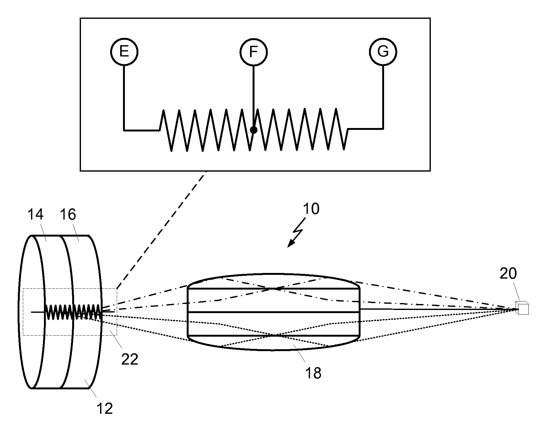
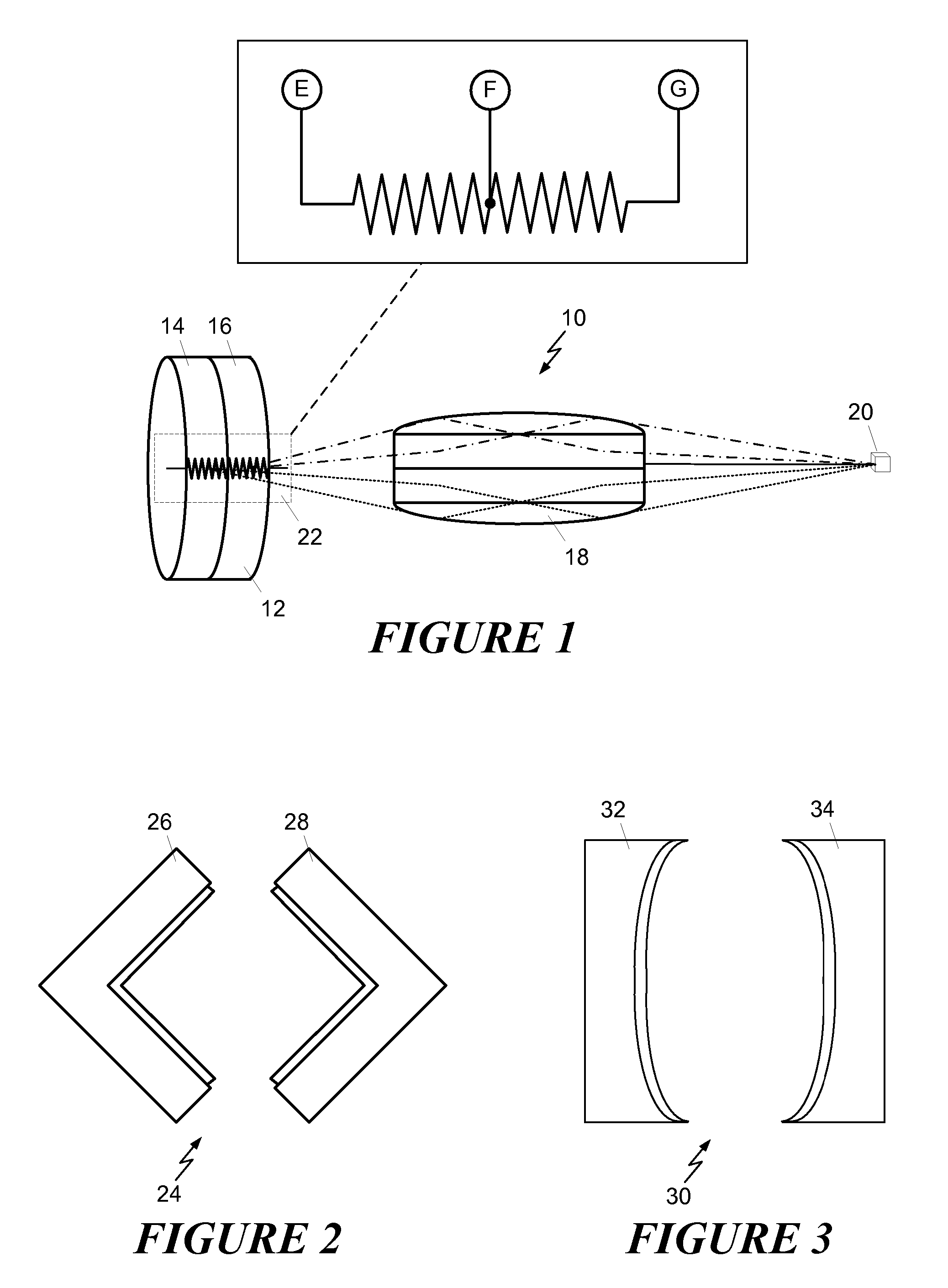
[0017] Shown in FIG. 1 is a schematic depiction of a multiple wavelength X-ray source 10 according to the present invention. The source uses a rotating anode 12 that has a target with two different materials. For example, a first section 14 could be made of copper, while a second section 16 could be made of molybdenum. Many other possible material combinations are also possible. The two target materials are chosen such that each provides a different characteristic X-ray wavelength when excited. Both rotate together, and are located relative to focusing optic 18 so that X-ray radiation from the anode may be received by the optic, and focused onto a sample 20 under investigation.

[0018] To provide selective wavelength generation, a two segment cathode 22 is located adjacent to the anode. In FIG. 1, an inset is provided that shows a larger view of the cathode. Three electrical terminals are connected to the cathode are shown and are labeled, respectively, “E”, “F” and “G”. By applying ...


PUM


Abstract

A multiple wavelength X-ray source includes an electron-generating cathode and an anode with multiple target regions, each of which emits X-rays at a different characteristic wavelength in response to the electrons. The different X-ray radiation outputs are focused by different focusing sections of a focusing optic. The multiple focusing sections are in different respective locations, and each focuses its respective X-ray radiation onto a sample. The focusing sections may be side-by-side mirrors in a Kirkpatrick-Baez configuration, or in a single-bounce, doubly curved elliptical configuration.

Description

FIELD OF THE INVENTION [0001] This invention relates generally to X-ray diffraction analysis and, more particularly, to X-ray sources used in X-ray diffraction analysis. BACKGROUND OF THE INVENTION [0002] X-ray diffraction analysis uses X-ray energy focused on a target material of interest to determine structural qualities of the material. For a particular material, and X-rays at a particular wavelength, the X-ray energy is diffracted and forms a diffraction pattern that may be detected with a detector to yield information regarding the material structure. Conventional X-ray sources are able to generate only a single wavelength as they rely on characteristic Kα radiation from a particular target material. That is, these sources function by illuminating a material target with a high energy electron beam. This excites both continuum Bremsstrahlung radiation and also characteristic line emission. For most analytical applications, a monochromator is used to isolate only the characterist...

Claims


Application Information

Patent Timeline
Patent Type & Authority Applications(United States)
IPC IPC(8): G21K1/06
CPCG01N23/20H01J2235/081H01J35/08G21K1/06H01J35/153
Inventor DURST, ROGER D.HE, BOB BAOPINGMICHAELSEN, CARSTENKATAYAMA, CHUJI
Owner BRUKER AXS
Why Eureka
Try Eureka