
Hydraumatic variable force buffer

A buffer and hydraulic technology, applied in the field of hydraulic variable force buffer, to achieve the effect of easy operation, low cost and simple structure

Inactive Publication Date: 2012-05-30
董芬芳
View PDF1 Cites 4 Cited by
  • Summary
  • Abstract
  • Description
  • Claims
  • Application Information

AI Technical Summary

Problems solved by technology

[0004] This door-closing buffer is easy to install, simple in structure, low in manufacturing cost, and can keep the door at a relatively consistent closing speed when the door-closing pressure is within a certain range; however, since the damping coefficient of the spring is constant, this The structure can only be applied when the external force changes little

Method used


Image

  • Hydraumatic variable force buffer
  • Hydraumatic variable force buffer
  • Hydraumatic variable force buffer

Examples


Embodiment Construction

[0026] The present invention will be further described below in conjunction with the accompanying drawings of the specification, but the scope of protection claimed by the present invention is not limited to the scope described in the embodiments.

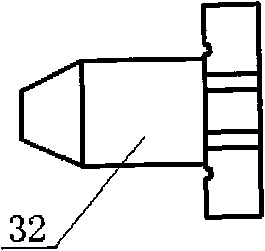
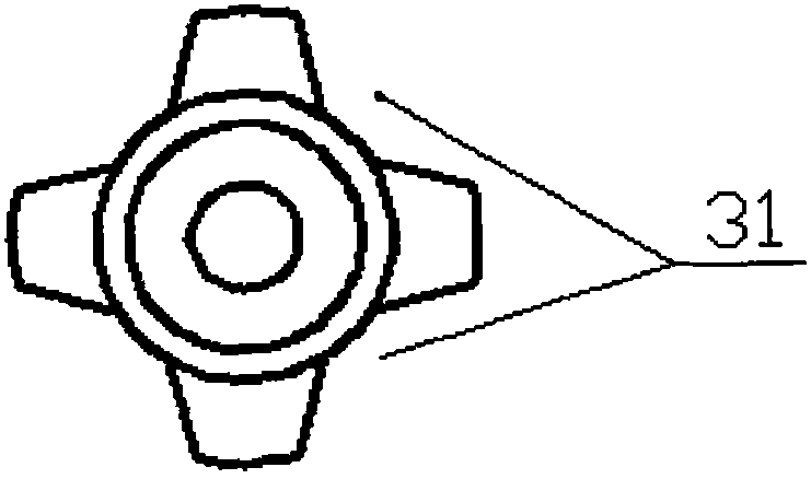
[0027] Such as figure 1 As shown, the hydraulic variable force buffer of the present invention includes an oil cylinder 1, a spring 2, a piston assembly, and a sealing system. The piston assembly includes a spring seat 3, a small convex flat ring 4, a small convex flat ring 12, a piston 5 and an iron rod 9. The sealing system includes an oil-absorbing sponge 6, an inner sleeve 11, a B-type sealing ring 7, an outer stopper 8, a small Y ring 13, and an energy-absorbing rubber head 10. The spring seat 3 has a protruding small shaft 32 inserted into the spring 2 hole to prevent the spring from sliding and increase the service life of the spring;

[0028] Such as figure 2 and image 3 As shown, the spring seat 3 is provided with four notch...


PUM


Abstract

The invention discloses a hydraumatic variable force buffer. The buffer comprises an oil cylinder, a spring, a piston assembly and a sealing system, wherein the spring, the piston assembly and the sealing system are all arranged in the oil cylinder, the spring is connected with the piston assembly, and the sealing system is arranged between the piston assembly and the inner wall of the oil cylinder. Compared with the prior art, the buffer provided by the invention has the following beneficial effects: when a door is closed, the buffer can dynamically generate corresponding counterforce according to the speed of the door and the magnitude of external force, the door can be smoothly closed so as not to make a sound; and 2, the structure is simple, the operation is easy, and the cost is cheap.

Description

Technical field [0001] The invention relates to a hydraulic variable force buffer. Background technique [0002] The door closing buffer in the prior art only uses spring resistance for buffering, and the damping coefficient is constant, and the resistance does not change according to the magnitude of the external force and its speed. [0003] The Chinese patent No. 200420110847.7 discloses a "door-closed buffer". The door-closed buffer includes a mounting frame and a buffer body. The buffer body includes a headgear and a jacket. The headgear and the jacket are plugged in, and the headgear and jacket are also equipped There is a locking mechanism to prevent the two from separating, and the head cover has a specific telescopic range relative to the outer cover; the inner wall of the head cover is provided with internal threads and springs. The rotating shaft is threaded with the head cover, and the rotating shaft has an external thread matching the internal thread. , The rear end o...

Claims


Application Information

Patent Timeline
Patent Type & Authority Applications(China)
IPC IPC(8): E05F3/10
Inventor 董芬芳
Owner 董芬芳
Learn More