Oscillating bar crank isolating valve

A cut-off valve and crank technology, applied to blast furnace parts, furnaces, heating furnaces, etc., can solve problems such as easy jamming, affecting operation, and high cost

Active Publication Date: 2009-09-09
SHILIN LUOHE METALLURGY EQUIP
View PDF1 Cites 3 Cited by
  • Summary
  • Abstract
  • Description
  • Claims
  • Application Information

AI Technical Summary

Problems solved by technology

[0002] In the ironmaking blast furnace hot blast stove system, a large number of medium and low temperature cut-off valves are used, such as cold air valve, combustion air cut-off valve, gas cut-off valve and flue valve, etc. Traditional valve products are mostly wedge-type gate valves, which have good sealing effect , long service life, but the disadvantage is that the structure is bulky, the installation space is large, and the cost is high
In order to change this situation, a cut-off butterfly valve appeared later, which is small in size and light in weight, but its sealing performance and service life are not ideal.
In the 1990s, a crank cut-off valve appeared on the market, such as the "gas cut-off valve" published by Chinese patent CN2197531Y. This valve has the structure and sealing performance of a gate valve. The upper part does not need to be equipped with a transmission frame. The internal transmission structure of the valve has a fatal flaw. The gate moves linearly along the track through the crank slider structure. After closing, it is greatly affected by temperature, and it is easy to get stuck at the moment of opening, which affects the normal smelting operation.

Method used


Image

  • Oscillating bar crank isolating valve
  • Oscillating bar crank isolating valve

Examples


Embodiment Construction

[0014] Embodiments of the present invention will be described below in conjunction with the accompanying drawings.

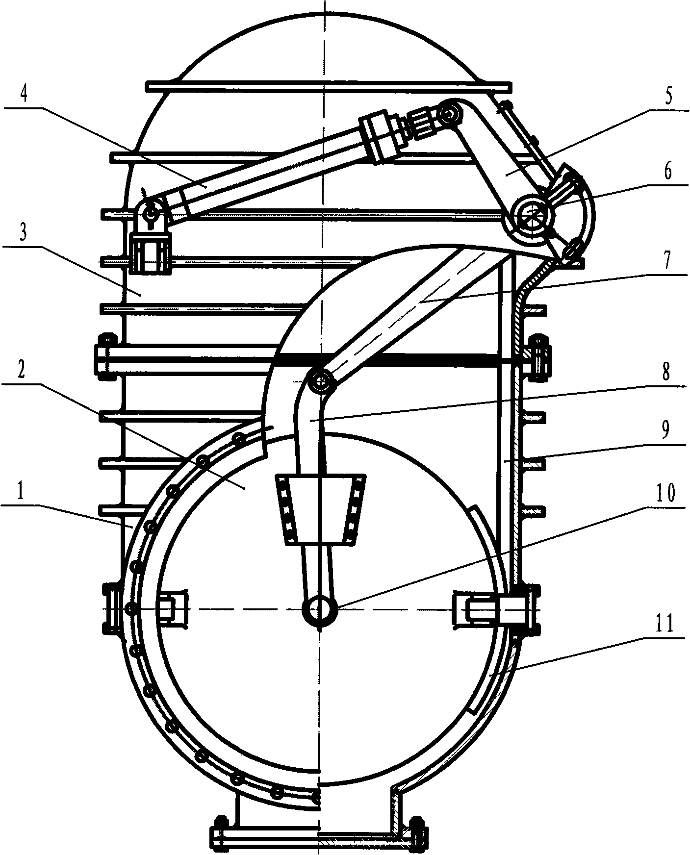
[0015] Such as figure 1 As shown: the crank cut-off valve includes a valve body 1, a valve cover 3, a gate plate 2 and a hydraulic drive device 4.

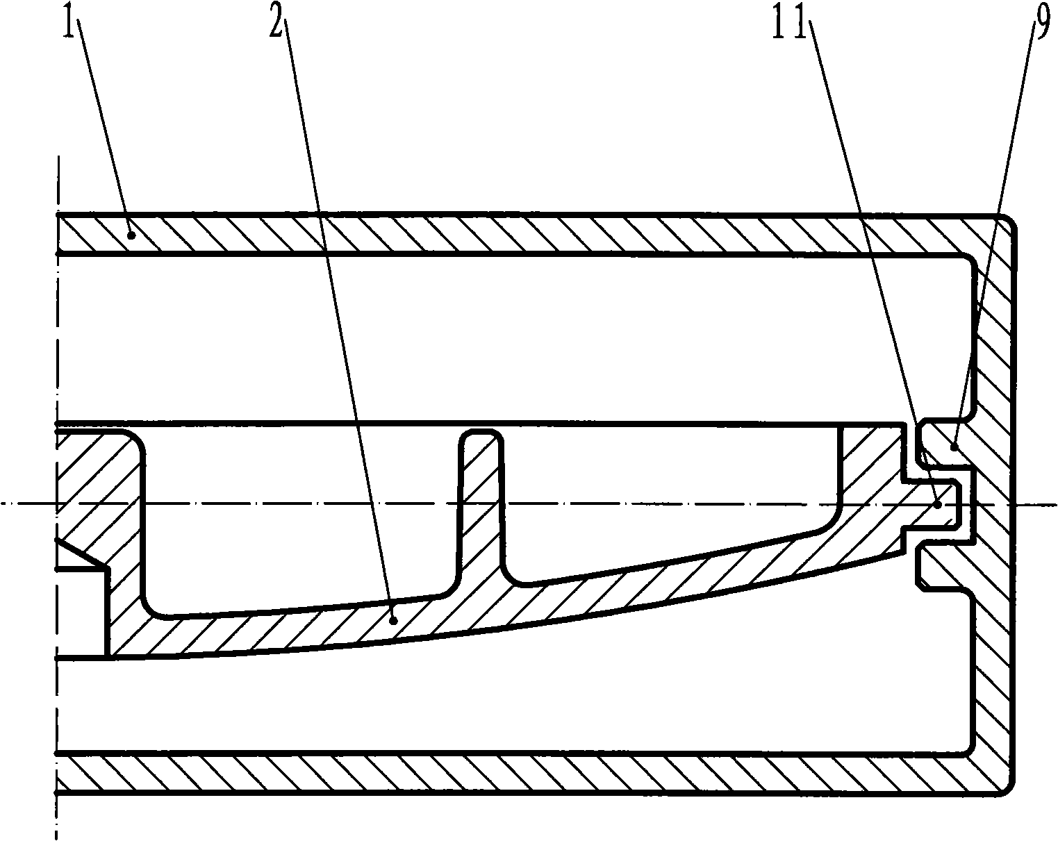
[0016] The opening and closing device of flashboard 2 is a crank swing rod mechanism, which includes crank 5, crank shaft 6, lever 7 and swing rod 8, crank 5, lever 7 and crank shaft 6 are fixedly connected by keys, and one end of lever 7 is connected with Fork 8 is hingedly connected, and the other end of fork 8 is hingedly connected with the shaft of flashboard 2 . The above-mentioned two hinges are equipped with self-lubricating bushings 10 . The drive device 4 is arranged on the valve cover 3 . A section of guide block 11 for rotating opening and closing is respectively provided on both sides of the flashboard 2, and a slideway 9 is correspondingly arranged on the valve body. The flashboard 2 and the guide b...


PUM


Abstract

The invention discloses an oscillating bar crank isolating valve, which comprises a valve body, a valve cover, a flashboard and a driving device. The opening and closing of the flashboard uses a crank oscillating bar structure which comprises a crank, a crank shaft, a lever and an oscillating bar; wherein, the crank, the lever and the crank shaft are fixedly connected; one end of the lever is connected with the oscillating bar by a hinge and the other end of the oscillating bar is connected with a flashboard shaft by the hinge. Guide pads used for rotating, opening and shutting are arranged at two sides of the flashboard. The valve body is correspondingly provided with a slide rail. The driving device moves to drive the crank and the lever to swing around the crank shaft and drive the oscillating rod to swing. The flashboard swings along the oscillating rod and upgrades, and the valve opens. The driving device returns stroke, and the valve closes. The flashboard has a rotation, opening and shutting process correspondingly to the valve body in the instant of opening and shutting while a flashboard guide rod and the guidance of the slide rail of the valve are rotatably matched, thus avoiding the occurrence of the deadlocking phenomenon of a wedge block of the flashboard. The valve has the advantages of good sealing property and long service life of the flashboard, small volume, light weight, operational safety and moderate cost and the like of a butterfly valve and can be suitable for parting off working condition of middle and low temperature medium in blast furnace ironmaking.

Description

technical field [0001] The invention relates to a cut-off valve used in blast furnace smelting, in particular to a swing rod crank cut-off valve. Background technique [0002] In the ironmaking blast furnace hot blast stove system, a large number of medium and low temperature cut-off valves are used, such as cold air valve, combustion air cut-off valve, gas cut-off valve and flue valve, etc. The traditional valve products are mostly wedge-type gate valves, which have good sealing effect , long service life, but the disadvantage is that the structure is bulky, the installation space is large, and the cost is high. In order to change this situation, a cut-off butterfly valve appeared later, which is small in size and light in weight, but its sealing performance and service life are not ideal. In the 1990s, a crank cut-off valve appeared on the market, such as the "gas cut-off valve" published by Chinese patent CN2197531Y. This valve has the structure and sealing performance o...

Claims


Application Information

Patent Timeline
Patent Type & Authority Applications(China)
IPC IPC(8): C21B9/12
Inventor 张进刘永刚王怀柱郭世卫唐宗巍郭宇张松涛
Owner SHILIN LUOHE METALLURGY EQUIP
Why Eureka
Try Eureka