Oil distribution axle linkage rod type hydraulic motor

A hydraulic motor and connecting rod type technology, applied in the field of hydraulic motors, can solve the problems such as the radial size of the rolling bearing unit cannot be increased at will, the bearing capacity of the rolling bearing unit cannot be increased, and the high pressure work requirements cannot be met, so as to prevent the oil stuffing phenomenon and reduce the Machining accuracy, cost saving effect

Inactive Publication Date: 2008-02-06
宁波欧易液压有限公司
View PDF1 Cites 14 Cited by
  • Summary
  • Abstract
  • Description
  • Claims
  • Application Information

AI Technical Summary

Problems solved by technology

But adopt this structure of rolling friction, although can preferably overcome the drawback of the radial crankshaft connecting rod type hydraulic motor that adopts hydrostatic balance sliding bearing, can also bring following problem thereupon: Due to crankshaft, bearing sleeve and The roller is located in the center of the hydraulic motor, and the plunger and connecting rod are distrib

Method used


Image

  • Oil distribution axle linkage rod type hydraulic motor
  • Oil distribution axle linkage rod type hydraulic motor
  • Oil distribution axle linkage rod type hydraulic motor

Examples


Example Embodiment

[0030] The present invention will be described in further detail below in conjunction with the embodiments of the drawings.

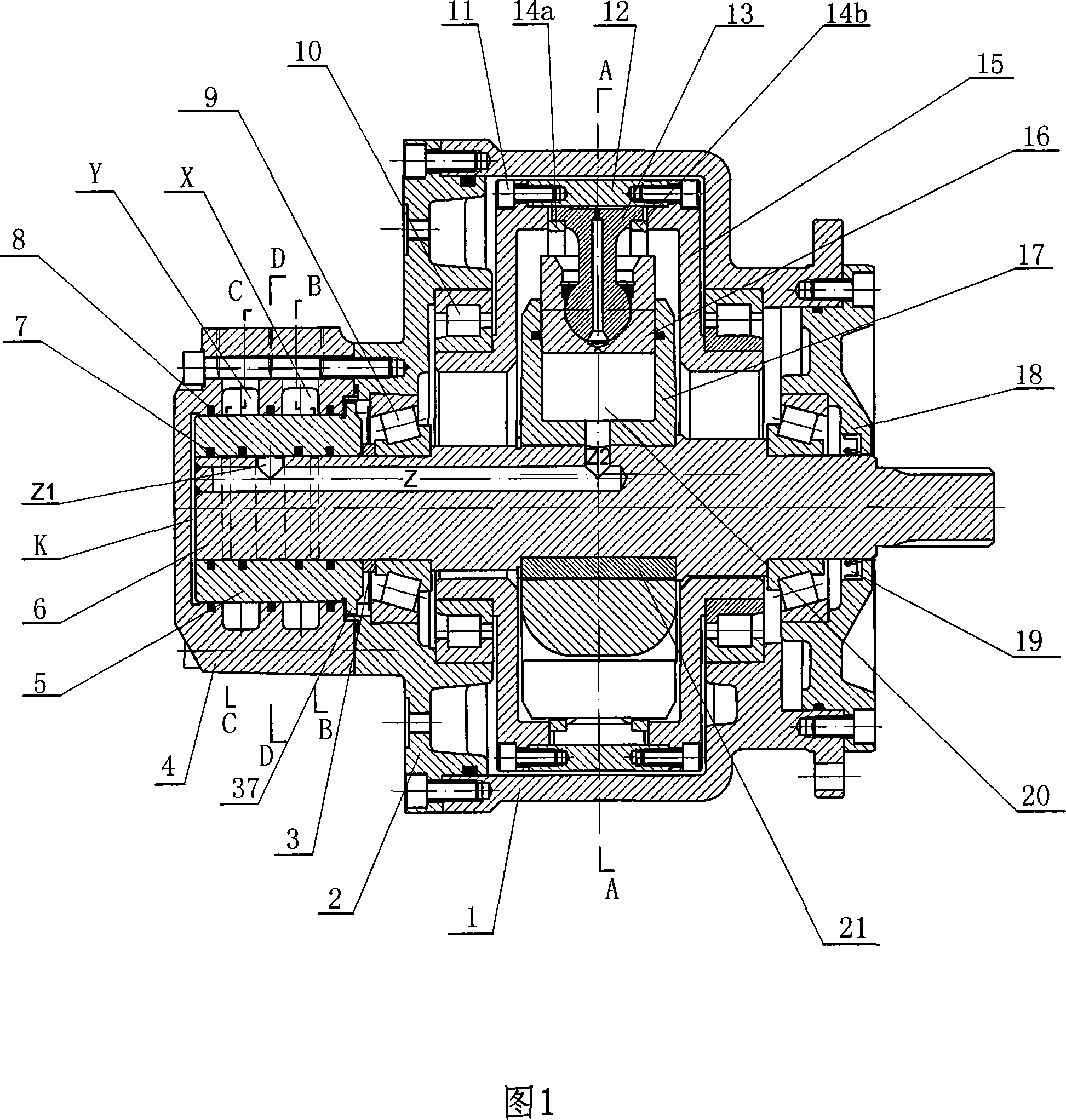
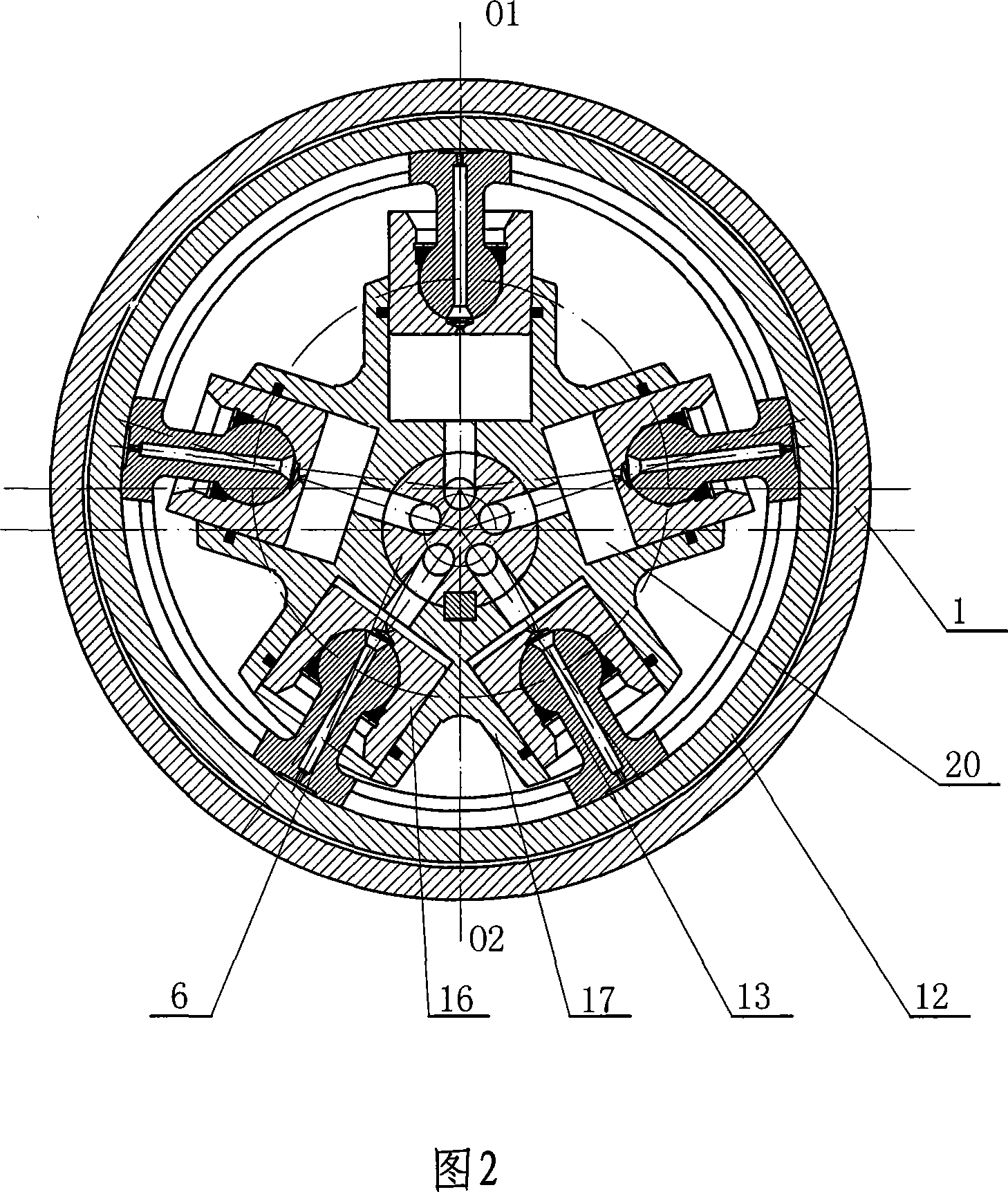
[0031]As shown in Figures 1 and 2, the connecting rod hydraulic motor includes a shell, a shaft oil distribution structure, a rotating shaft 6, five plunger-connecting rod assemblies, and a rotating sleeve 12. The shell consists of a shell 1 and a bolt The front cover 18 and the rear cover 2 fixed to the housing are composed of; the shaft oil distribution structure is composed of an oil pan 4 fixed on the rear cover 2 by bolts and an oil distribution sleeve 5 located in the oil pan; The rotating shaft 6 is eccentrically placed in the inner cavity of the housing, and is supported on the front cover 18 and the rear cover 2 through the first set of roller bearings 9. One end of the rotating shaft is sleeved with the above-mentioned oil distribution sleeve 5, and a positioning ring is used 3 The oil distribution sleeve is axially limited, and at the same time, ...


PUM


Abstract

A shaft-distribution-oil link-type oil hydraulic motor is improved on the basis of the original shell, the shaft-distribution-oil configuration, the rotating shaft, and the plunger piston-link assembly, etc., namely that the shaft-distribution-oil configuration consists of an oil-through disk and an oil distribution jacket. No.1 and No.2 hydraulic fluid ports are opened on the oil-through disk, and No.1 and No.2 ring grooves are opened on one of the interfaces of the oil-through disk and the oil distribution jacket to airproof and form No.1 and No.2 oil reservoirs; at the same time, No.1 and No.2 under cut slots which are separated by the contact crown faces are symmetrically opened on the same ring face of the inner wall of the oil-through jacket. The No.1 and No.2 under cut slots are arranged between the No.1 and No.2 oil reservoirs to airproof and form the No.1 and No.2 main oil reservoirs. A plurality of flow passages corresponding to the main oil reservoirs and connected with the plunger piston are arranged on the rotating shaft. The adopted structure forms the oil-through configuration and the oil distribution configuration into adjacency configurations, approximately distributing in the same orientation to greatly decrease the axial size of the oil distributor, and make the structure of the oil hydraulic motor closer and more reasonable.

Description

technical field [0001] The invention relates to a hydraulic motor, in particular to a shaft oil connecting rod hydraulic motor. Background technique [0002] A radial crankshaft connecting rod hydraulic motor with hydrostatically balanced sliding bearings includes a housing consisting of a cover and housing, an oil distributor with multiple oil distribution holes, a plunger cylinder, a plunger-connecting rod assembly and a crankshaft, Among them, the oil distributor is divided into plane oil distribution structure and shaft oil distribution structure. For example, edited by Lei Tianjue, the first volume of "Newly Edited Hydraulic Engineering Handbook" published by Beijing Institute of Technology Press in December 1998, on pages 505 to 507 and Figure 12.4-3, a crankshaft coupling with a shaft oil distribution structure is disclosed. Rod type hydraulic motor, the crankshaft of the hydraulic motor is supported in the shell and cover through bearings, one end of the crankshaft ...

Claims


Application Information

Patent Timeline
IPC IPC(8): F03C1/247F03C1/04
Inventor 黄孝正胡康梁
Owner 宁波欧易液压有限公司
Why Eureka
Try Eureka