Motor and connection structure of end covers and bearings thereof

A connection structure and bearing technology, applied in the direction of casing/cover/support, electromechanical device, electrical components, etc., can solve the problems of motor noise and vibration, deformation of bearing inner hole, motor stuck in operation, etc., to reduce working noise and Vibration, ensure coaxiality, avoid the effect of stuck

Active Publication Date: 2014-12-03
ZHEJIANG SANHUA COMMERCIAL REFRIGERATION CO LTD
View PDF7 Cites 12 Cited by
  • Summary
  • Abstract
  • Description
  • Claims
  • Application Information

AI Technical Summary

Problems solved by technology

First of all, during the press-fit process between the bearing and the end cover, the inner hole of the bearing is deformed, and the deformation amount and deformation form are not easy to control, so that there is a deviation in the matching gap between the inner hole of the bearing and the rotating shaft, and the end cover 30 passes through the stator (in the figure not shown), the other end cover is assembled with the rotating shaft 10, thus, there is a risk of jamming during the operation of the motor
Secondly, the end cover 30 is machined, and the machining accuracy and dimensional tolerance directly affect the interference fit relationship between it and the bearing, and the coaxiality is poor, which may cause excessive noise and vibration of the motor

Method used


Image

  • Motor and connection structure of end covers and bearings thereof
  • Motor and connection structure of end covers and bearings thereof
  • Motor and connection structure of end covers and bearings thereof

Examples


Embodiment 1

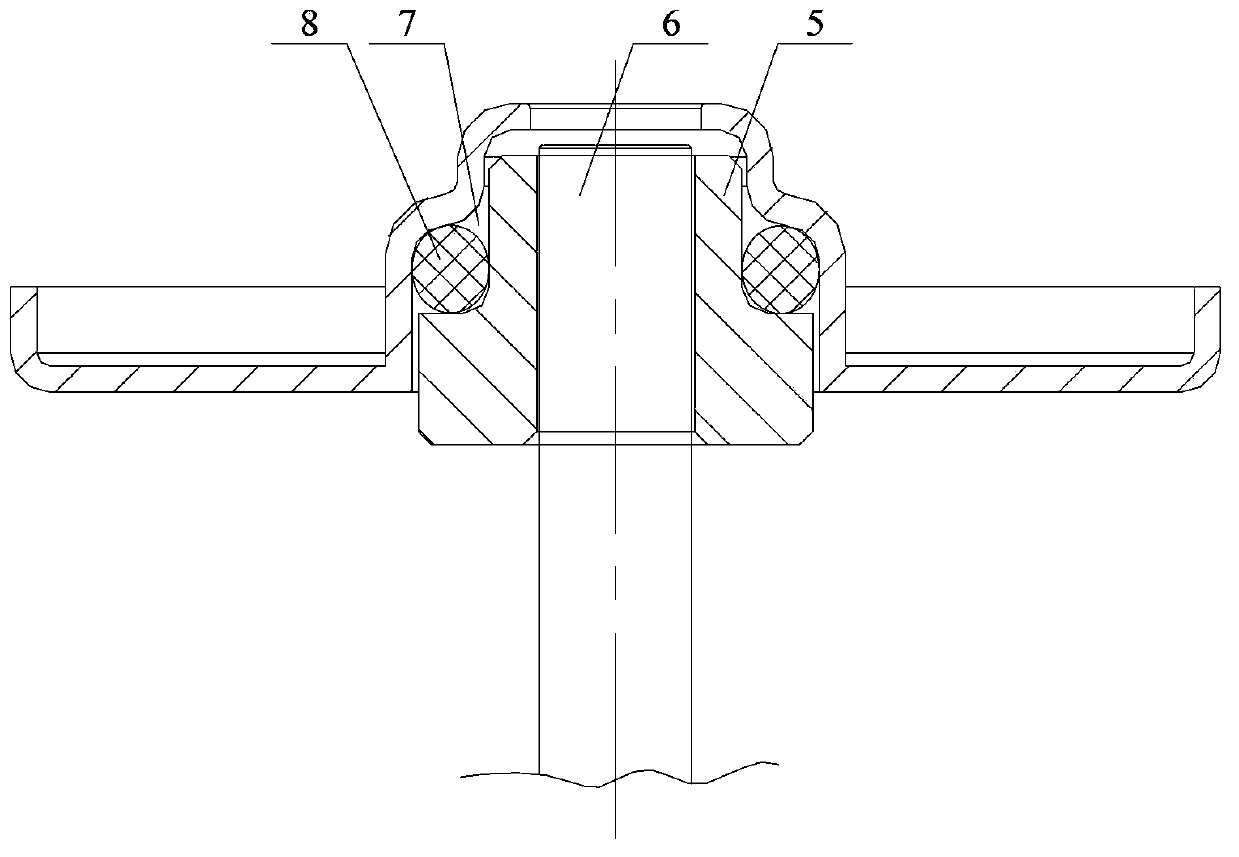
[0033] Please also see image 3 , which shows a schematic diagram of a connection structure between a bearing and an end cover.

[0034] In this solution, the radial cross-sections of the bearing cavity on the bearing 5 and the end cover are all in the shape of an inverted "T" shape with a small upper part and a larger lower part, and the steps on the bearing 5 are located below the steps on the inner wall of the bearing cavity; the aforementioned The annular accommodation portion 7 for accommodating the elastic support member 8 is formed between the small diameter section of the bearing 5 and the large diameter section of the bearing cavity between the two steps.

[0035] Here, the elastic support member 8 is preferably made of rubber material, which can meet the requirements of load bearing and self-adaptive deformation on the one hand, and at the same time, the manufacturing cost is controllable. The elastic support member 8 can be designed according to the external dimens...

Embodiment 2

[0039] See Figure 4 , which is a schematic diagram of the connection structure between the bearing and the end cover in the second embodiment. In order to clearly show the difference between this embodiment and the first embodiment, the same components are marked with the same symbols. The following examples are the same.

[0040] In this solution, the radial sections of the bearing 5 and the bearing cavity are both in the shape of a "T" shaped step with a large upper part and a smaller lower part, and the step on the bearing 5 is located above the step of the bearing cavity; the aforementioned is used to accommodate the elastic support The annular housing portion 7 of the member 8 is formed between the small diameter section of the bearing 5 and the large diameter section of the bearing cavity between the two steps.

Embodiment 3

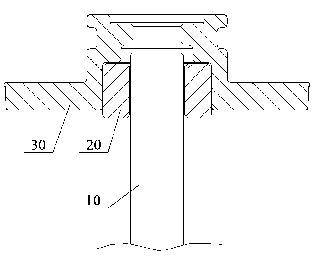
[0043] See Figure 5 , which is a schematic diagram of the connection structure between the bearing and the end cover described in the third embodiment.

[0044] In this solution, the radial section of the bearing 5 is in the shape of "I"; the aforementioned annular accommodation part 7 for accommodating the elastic support 8 is formed on the outer surface of the bearing 5 in the "I"-shaped recess and the bearing cavity between the cylindrical inner walls.

[0045] Compared with the first and second embodiments, when the O-ring is used as the elastic support member 8, it is fitted in the inner recess of the outer surface of the bearing 5, and the relative position of the two will not be shifted axially, and the assembly operation is facilitated .


PUM


Abstract

The invention discloses a connection structure of end covers and bearings. Each end cover is provided with a bearing cavity for accommodating a corresponding bearing. Annular accommodating parts are formed between the inner walls of the bearing cavities and the outer surfaces of the bearings. Precompression elastic support parts are arranged in the annular accommodating parts, and radial gaps are arranged between the bearing cavities and the bearings. Through an optimization design, deformation of bearing bores after assembly completion is not generated so that cooperation of the bearings with a rotating shaft is not affected and thus happening of a jamming phenomenon in an operation process of a motor is prevented completely. At the same time, the elastic connectors between the end covers and the bearings are capable of using deformable characteristics to realize automatic self-aligning so that coaxiality of the members is ensured and a reliable guarantee is provided to reduction of work noises and vibration of the motor. On the basis, the invention provides the motor which applies the connection structure.

Description

technical field [0001] The invention relates to the structural technology of a driving motor, in particular to a motor and its end cover bearing connection structure. Background technique [0002] As the power source of the liquid medium circulation system, the driving motor of the circulating pump must adopt a shielded structure to ensure the stability of the operation without leakage. In the prior art, the motor shaft rotating synchronously with the internal rotor is connected to the external stator through the upper and lower end covers respectively to achieve relative sealing. [0003] See figure 1 , which shows a schematic diagram of the assembly relationship of the existing motor shaft, bearing and end cover. [0004] As shown in the figure, the rotating shaft 10 is connected with the end cover through the bearing 20 . Wherein, the bearing 20 is press-fitted into the end cover 30 obtained by machining, which is limited by the structure of the bearing and the end cov...

Claims


Application Information

Patent Timeline
Patent Type & Authority Applications(China)
IPC IPC(8): H02K5/16H02K5/24
Inventor 不公告发明人
Owner ZHEJIANG SANHUA COMMERCIAL REFRIGERATION CO LTD
Why Eureka
Try Eureka