
Filter for fuel

A filter and fuel technology, applied to liquid fuel feeders, charging systems, machines/engines, etc.

Inactive Publication Date: 2014-07-02
NIFCO INC
View PDF7 Cites 0 Cited by
  • Summary
  • Abstract
  • Description
  • Claims
  • Application Information

AI Technical Summary

Problems solved by technology

Therefore, in the technology of the above-mentioned Patent Document 1, which makes it difficult to make the distance between the surface and the back surface of the filter member small, the flow path through which the filtered fuel flows can be ensured reliably, but the bending of the filter member is increased. There is still room for improvement in terms of sex

Method used


Image

  • Filter for fuel
  • Filter for fuel
  • Filter for fuel

Examples


Embodiment Construction

[0030] Next, one embodiment of the fuel filter of the present invention will be described with reference to the drawings. First, the structure of the fuel supply device used in the fuel filter will be described.

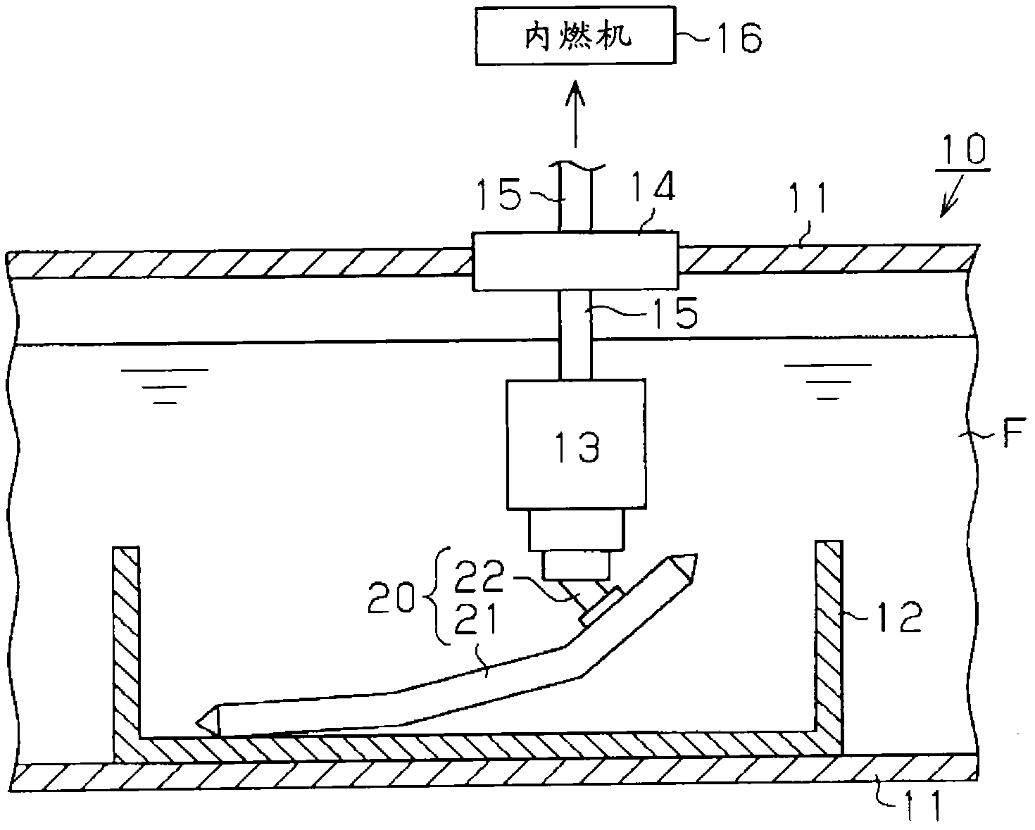
[0031] Such as figure 1As shown, inside a fuel tank 11 constituting the fuel supply device 10 , a chamber 12 formed in the shape of a tank with a bottom is fixed. A part of the fuel F in the fuel tank 11 is stored in the chamber 12 , and a fuel filter 20 for filtering the fuel F is accommodated. The fuel filter 20 has one end in contact with the bottom wall of the chamber 12 and the other end bent away from the bottom wall of the chamber 12 . A fuel pump 13 for sucking fuel F is connected to the other end portion of the fuel filter 20 . The fuel pump 13 is connected to an internal combustion engine 16 through a supply pipe 15 fixed to a flange portion 14 of the fuel tank 11 . Then, when the fuel pump 13 is driven, the fuel F in the chamber 12 is filtered around t...


PUM


Abstract

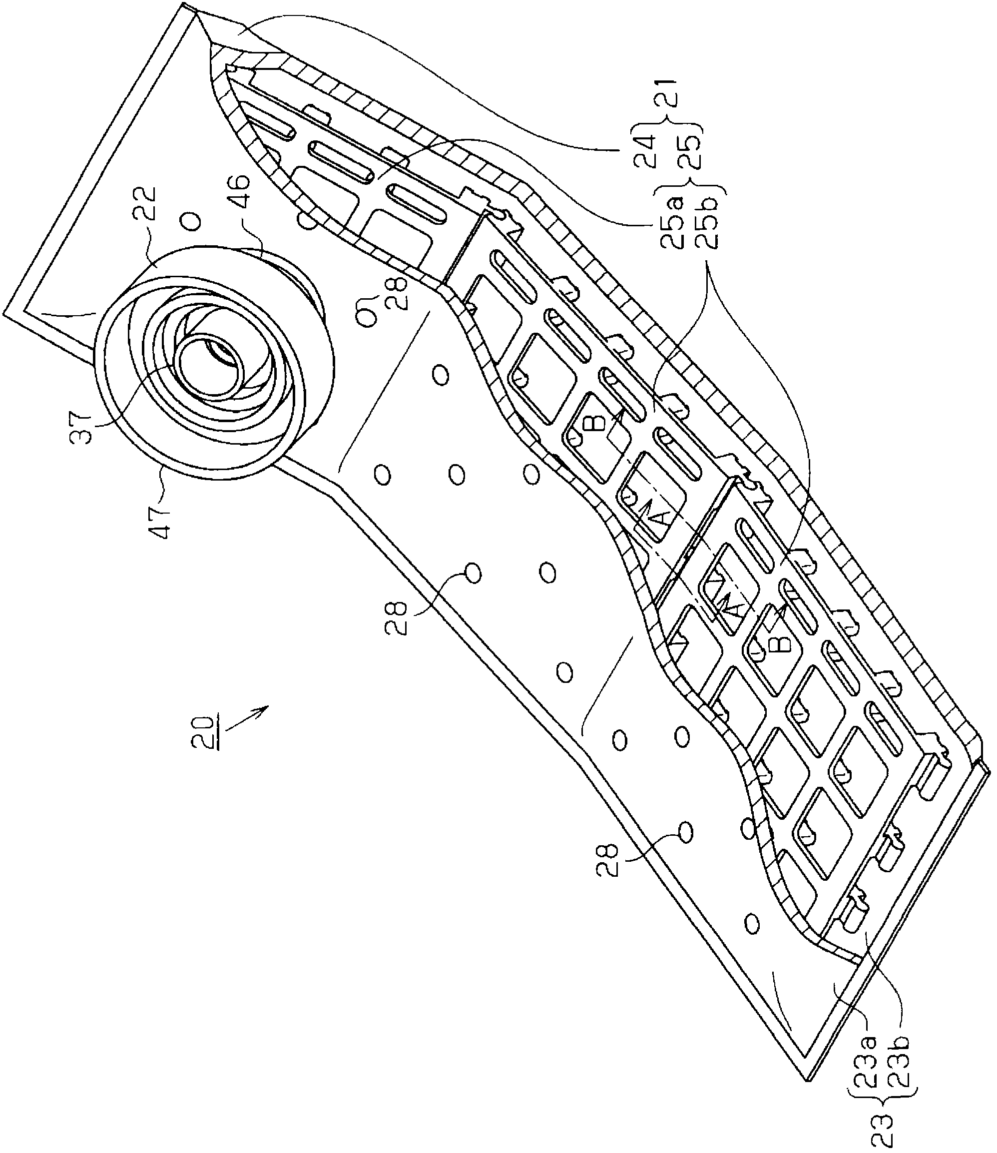
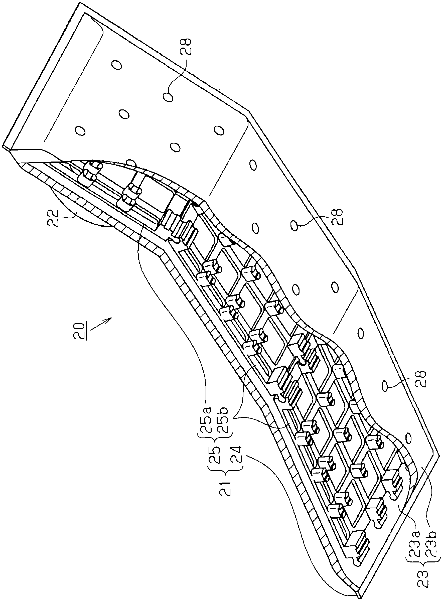
Provided is a filter for fuel, capable of ensuring the passageway for fuel flowing inside a filter member and improving the bendability of the filter member. The filter (20) comprises: a flat-bag like filtering member (24) made of filtering sheets and a support frame (25) supporting the filtering member (24) from the inner side of the filtering member (24), wherein the support frame (25) is formed by connecting a plurality of plate-shaped frame-forming members; the frame-forming member is provided with a clamping portion having a concave arc cross section at the outboard of an edge portion and a clamped portion having a raised arc cross section at the outboard of another edge portion; and of the adjacent frame-forming members, the clamped portion of one frame-forming member is clamped by the clamping portion of the other frame-forming member.

Description

technical field [0001] The present invention relates to a fuel filter arranged in a fuel tank. Background technique [0002] Conventionally, as described in Patent Document 1, a fuel filter having a filter member formed into a flat bag shape by a filter sheet is known. In such a fuel filter, in order to ensure the internal space of the filter member, a support frame is usually built into the filter member to support the filter sheet on the front side and the filter sheet on the rear side from the inside of the filter member. [0003] In the above-mentioned support frame, the surface on the front side of the support frame and the filter sheet on the front side of the filter member face each other, and the surface on the back side of the support frame and the filter sheet on the back side of the filter member face each other. The method is built into the filter element. With such a configuration, the distance between the filter sheet on the front side and the filter sheet on...

Claims


Application Information

Patent Timeline
Patent Type & Authority Patents(China)
IPC IPC(8): F02M37/22
Inventor 池内彰吾
Owner NIFCO INC
Learn More