Space wedge type irreversible transmission device and whole active driving lifting mechanism
A kind of transmission device and space technology, applied in hoisting device, clockwork mechanism, clutch, etc., can solve the problems that the safety is difficult to be effectively guaranteed, and the rotating speed of the reel is not easy to stabilize, etc.
- Summary
- Abstract
- Description
- Claims
- Application Information
AI Technical Summary
Problems solved by technology
Method used
Image
Examples
Embodiment 1
[0051] Embodiment 1: Space wedging type bidirectional irreversible transmission device D1 with a single intermediary
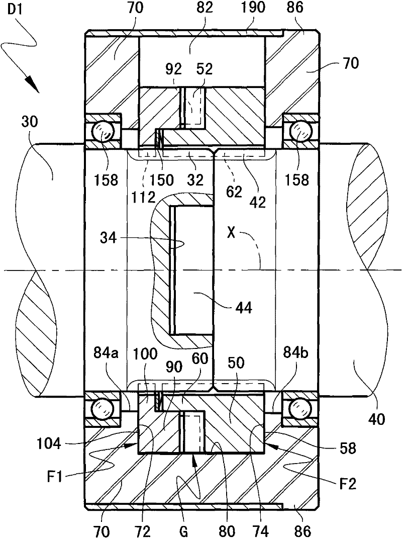
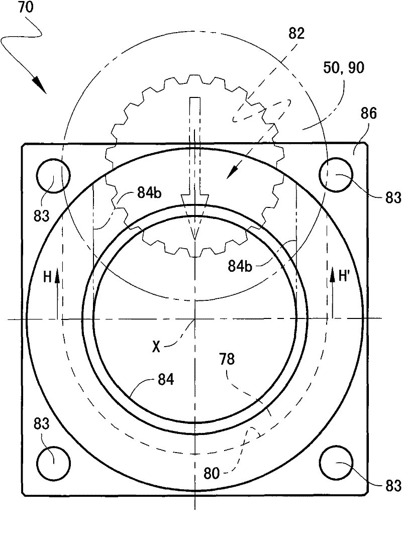
[0052] see Figure 1~2 , 8A-8B, the two-way irreversible transmission device D1 has a shaft-shaft transmission form, which includes a guide member 50 that is optimally formed around the axis X and is optimally stepped and annular. On the inner end surface of the outer ring side, a group of helical guide teeth 52 that are optimally uniformly distributed around the axis X are arranged; The force transmission protruding teeth 62, which are spline teeth, are non-rotatably connected with the shaft-shaped driving piece 30 and the driven piece 40 coaxially arranged in the inner hole thereof by means of a spline pair. The former connection has a circumferential degree of freedom εg greater than zero, the latter connection optimally has a circumferential degree of freedom equal to zero. Correspondingly, at least one toggle tooth 32 and a force transmission protruding...
Embodiment 2
[0091] Embodiment 2: Space wedging type two-way irreversible transmission device D3 with combined intermediary parts on the same side
[0092] Such as Figure 4 , 9 As shown, transmission D3 can be regarded as a modification of transmission D1.
[0093] Firstly, the shell-type friction member 70 of the transmission device D3 is transformed into a composite member composed of two semi-circular shell-type force-limiting elements 160a, 160b that are at least roughly symmetrical in the radial direction, butted radially, and are tightly hooped with interference. At least one annular hoop 170 on its outer peripheral surface is fastened as a whole. The hoop 170 is optimally fixedly connected to a frame / seat not shown. In fact, the two force-limiting elements 160a, 160b are the ring-shaped ring members provided with the disc-shaped ring-shaped full-circumferential groove 78 on the inner peripheral surface 84, and are optimally divided into two completely symmetrical semicircles in ...
Embodiment 3
[0101] Embodiment 3: Space wedging type two-way irreversible transmission device D4 with combined intermediaries on different sides
[0102] see Figure 5 , 10 , the main improvement of the transmission device D4 relative to the transmission device D1 is that it imitates the two best ring-shaped intermediary parts 90a and 90b of the transmission device D3, respectively provided with one-way guide teeth 92a and 92b, and the circumferential directions are opposite to each other. are arranged at both axial ends of the guide member 50 respectively. The minimum axial distance defined by the two opposite rotating friction surfaces 104a and 104b of the two members is smaller than the axial distance defined by the corresponding two opposite traction friction surfaces 72a and 72b. That is, there is no force transmission friction mechanism F2 in the transmission device D4, but only two symmetrical traction friction mechanisms F1a and F1b. Correspondingly, two sets of sawtooth-shaped ...
PUM
| Property | Measurement | Unit |
|---|---|---|
| The inside diameter of | aaaaa | aaaaa |
| Outer diameter | aaaaa | aaaaa |
| Axial width | aaaaa | aaaaa |
Abstract
Description
Claims
Application Information
 - R&D
- Intellectual Property
- Life Sciences
- Materials
- Tech Scout
- Unparalleled Data Quality
- Higher Quality Content
- 60% Fewer Hallucinations
Browse by: Latest US Patents, China's latest patents, Technical Efficacy Thesaurus, Application Domain, Technology Topic, Popular Technical Reports.
© 2025 PatSnap. All rights reserved.Legal|Privacy policy|Modern Slavery Act Transparency Statement|Sitemap|About US| Contact US: help@patsnap.com


